Construction method of prefabricated external wall jointed drainage pipe of prefabricated concrete building

A concrete building and construction method technology, applied in the direction of buildings, building components, sustainable buildings, etc., can solve problems such as low work efficiency, difficult to clean, and unsightly, so as to improve efficiency, avoid tediousness and unevenness, and save manpower and material resources Effect

Active Publication Date: 2022-05-17
刘闪闪
View PDF21 Cites 0 Cited by
  • Summary
  • Abstract
  • Description
  • Claims
  • Application Information

AI Technical Summary

Problems solved by technology

The foam strips are placed in the joints of the prefabricated external walls and the sealing layer is set to form a drainage cavity. The water flows into the joints of the prefabricated external walls and flows down along the foam strips. Using the principle of one-way drainage of the drainage pipes, the drainage cavity is divided due to The condensed water generated when the internal and external temperatures are not consistent is discharged. Although this device has many beneficial effects, the following problems still exist: this method manually puts the laitance into the seam, and it is easy to cause the laitance to splash out and adhere to the outside of the seam It is extremely difficult to clean, and it is difficult to ensure that the outside of the joint is smooth and clean, and it is difficult to ensure that the outside of the joint is flat and clean. Construction method of patchwork drainage pipe for building prefabricated exterior wall

Method used


Image

  • Construction method of prefabricated external wall jointed drainage pipe of prefabricated concrete building
  • Construction method of prefabricated external wall jointed drainage pipe of prefabricated concrete building
  • Construction method of prefabricated external wall jointed drainage pipe of prefabricated concrete building

Examples


Embodiment Construction

[0035] In describing the present invention, it should be understood that the terms "center", "longitudinal", "transverse", "length", "width", "thickness", "upper", "lower", "front", " Orientation indicated by rear, left, right, vertical, horizontal, top, bottom, inside, outside, clockwise, counterclockwise, etc. The positional relationship is based on the orientation or positional relationship shown in the drawings, and is only for the convenience of describing the present invention and simplifying the description, rather than indicating or implying that the referred device or element must have a specific orientation, be constructed and operated in a specific orientation, Therefore, it should not be construed as limiting the invention.

[0036] In the description of the present invention, "plurality" means two or more, unless otherwise specifically defined.

[0037]In the description of the present invention, it should be noted that, unless otherwise specified and limited, th...


PUM


Abstract

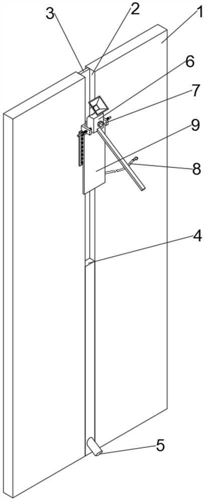
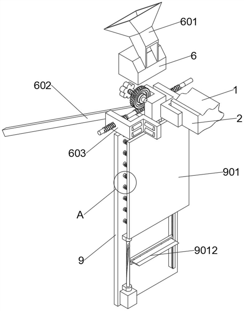
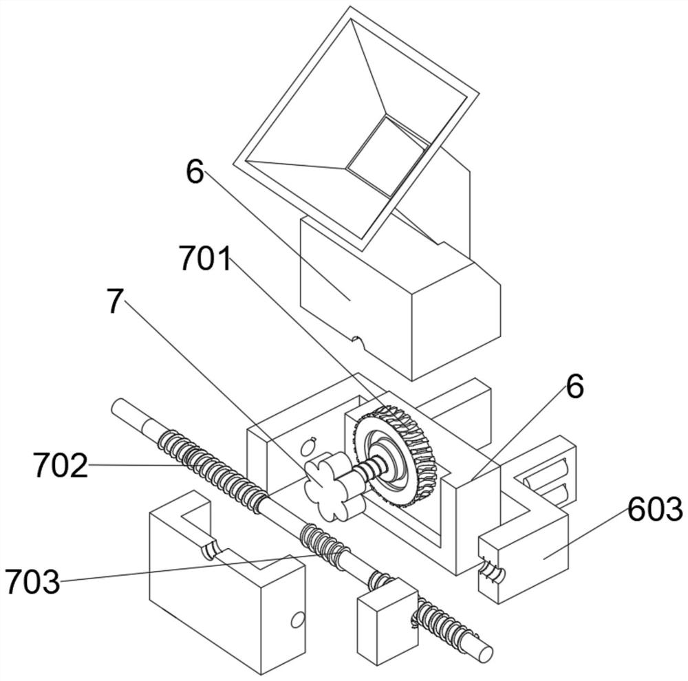
The invention discloses a construction method for a spliced ​​joint drainage pipe of a prefabricated external wall of an assembled concrete building, and belongs to the technical field of building construction. The construction method of the prefabricated external wall joint drainage pipe of the prefabricated concrete building is based on a construction sealing equipment for the prefabricated external wall joint drainage pipe of the prefabricated concrete building, and the prefabricated external wall joint drainage pipe construction sealing of the prefabricated concrete building The equipment includes the wall, the output end of the motor extends from the inside of the fixed ear to the outside and is coaxially connected with a cylinder. Through the cooperation of the cylinder cam and the middle part of the rear side of the adjustment block, the scraper is connected with the rotation of the pin shaft. The close cooperation between the structures makes When pouring laitance, there will be no laitance splashing and adhesion on the outside of the joint, avoiding laitance splashing and not easy to clean, ensuring the integrity and beauty of the wall, and avoiding manual scraping For cumbersome and uneven situations, the automatic scraper can be used to scrape the surface to make the whole more even and can be integrated with the entire wall.

Description

technical field [0001] The invention relates to the technical field of building construction, and more specifically, relates to a construction method for a spliced ​​joint drainage pipe on a prefabricated exterior wall of a prefabricated concrete building. Background technique [0002] In the waterproof system of the prefabricated external walls of prefabricated concrete buildings, the design concept is always that drainage is better than water blocking. Therefore, in order to realize the integrity of the waterproof function of the building, the drainage function of the cavity must be realized. However, today’s prefabricated concrete buildings Drainage is still not enough attention, and most of the waterproof function of buildings is entrusted to the waterproofing of materials. However, when the temperature inside and outside the drainage cavity is inconsistent, condensed water may be generated in the cavity, and even when the sealant of the outer wall is damaged or the bondi...

Claims


Application Information

Patent Timeline
Patent Type & Authority Patents(China)
IPC IPC(8): E04B1/70E04B1/68E04B1/682E04B1/684
CPCE04B1/70E04B1/68E04B1/6801E04B1/6806Y02B30/00
Inventor 刘闪闪李霞魏建军李伟李建高峰王进忠
Owner 刘闪闪
Why Eureka
Try Eureka