
Automatic rubber cutting equipment and automatic rubber cutting method

A glue-cutting and automatic technology, applied in metal processing and other directions, can solve the problems of high safety hazard, poor adjustability, and easy adhesion of rubber to the blade, so as to avoid damage.

Active Publication Date: 2019-02-15
德清通亚硅胶有限公司
View PDF7 Cites 10 Cited by
  • Summary
  • Abstract
  • Description
  • Claims
  • Application Information

AI Technical Summary

Problems solved by technology

[0003] In order to make up for the deficiencies of the prior art, the present invention provides an automatic rubber cutting device, which can solve the problems of poor adjustability, easy adhesion of rubber to the blade, and the need for manual cleaning in the existing rubber cutting process. There are many potential safety hazards and the rubber position is not easy to control. It can realize the function of automatic rubber cutting. It has the advantages of flexible adjustment, rubber is not easy to adhere to the blade, no need to manually clean the blade, high safety and the rubber position is not easy to change.

Method used


Image

  • Automatic rubber cutting equipment and automatic rubber cutting method
  • Automatic rubber cutting equipment and automatic rubber cutting method
  • Automatic rubber cutting equipment and automatic rubber cutting method

Examples


Embodiment Construction

[0020] In order to make the technical means, creative features, goals and effects achieved by the present invention easy to understand, the present invention will be further described below in conjunction with specific illustrations.

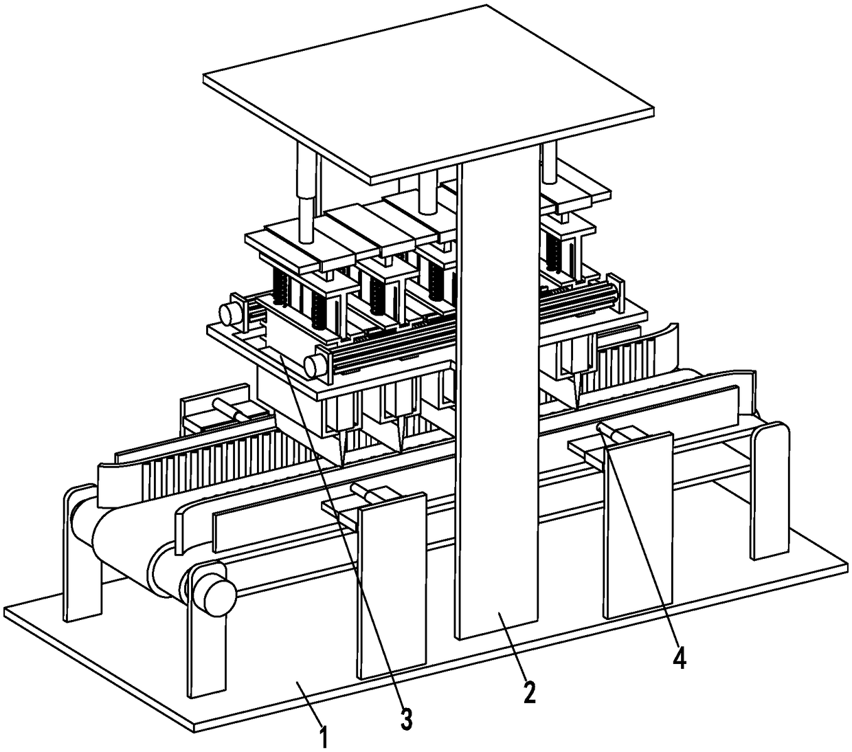
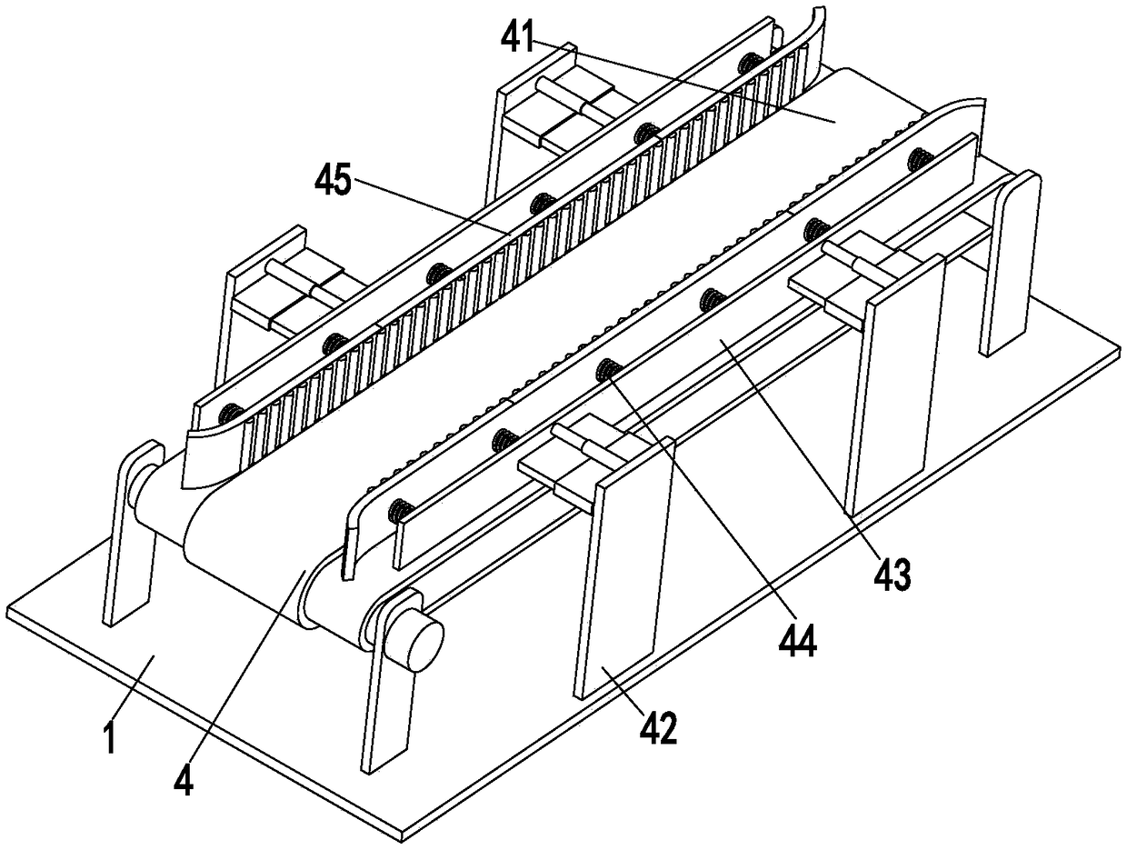
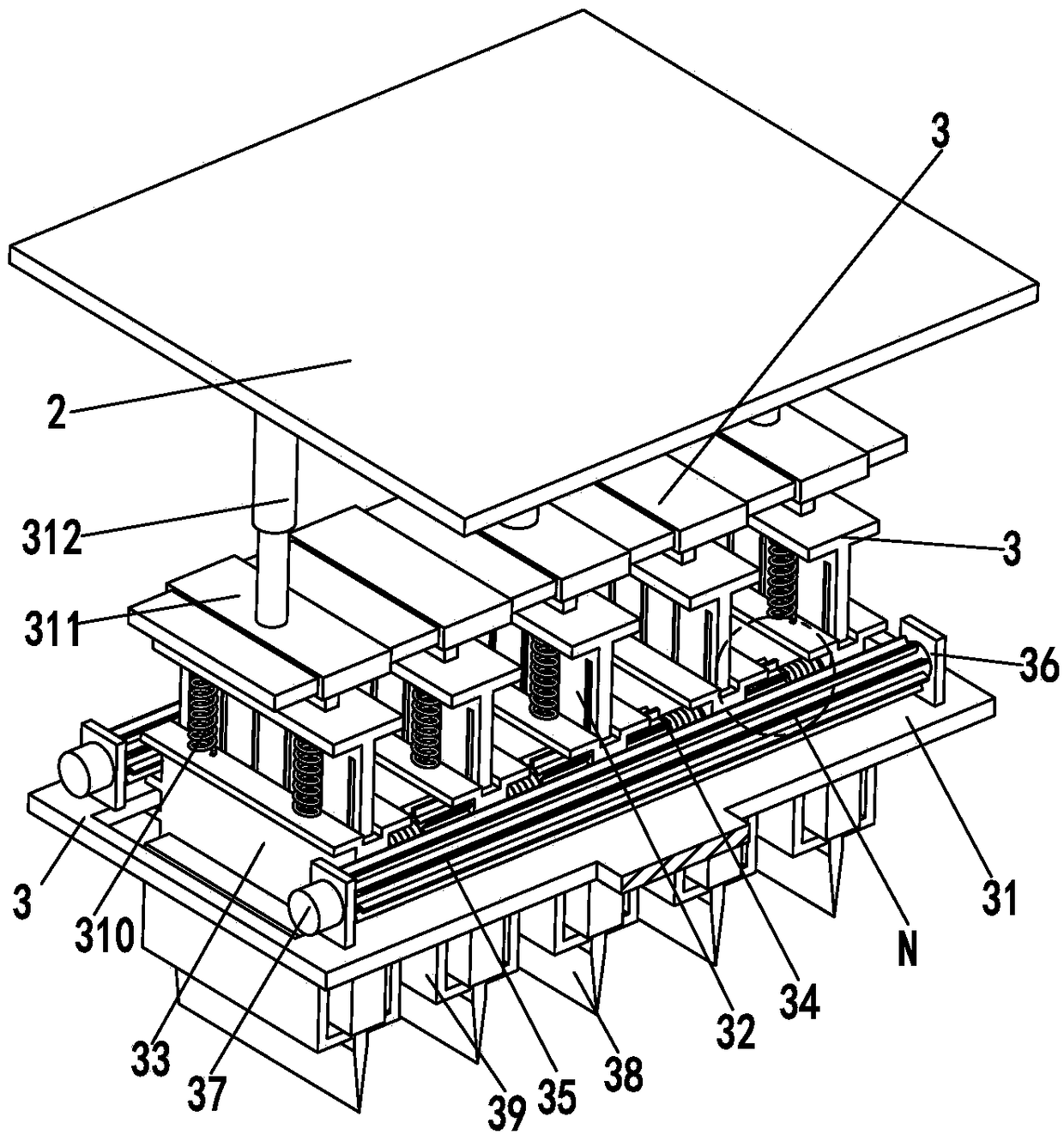
[0021] Such as Figure 1 to Figure 4 As shown, a rubber automatic cutting equipment includes a bottom plate 1, a mounting frame 2, a rubber cutting device 3 and a conveying device 4, the bottom plate 1 is equipped with a mounting frame 2, the mounting frame 2 is an inverted U-shaped structure, and the mounting frame 2 The lower end is provided with a sliding groove, and a glue cutting device 3 is installed in the sliding groove, and a conveying device 4 is arranged at the lower end of the glue cutting device 3, and the conveying device 4 is installed on the bottom plate 1; wherein:

[0022]The glue cutting device 3 includes a base plate 31, a fixed knife rest 32, an adjusting knife rest 33, an adjusting frame 34, an adjusting gear 35, a mounting...


PUM


Abstract

The invention relates to automatic rubber cutting equipment and an automatic rubber cutting method. The automatic rubber cutting equipment comprises a bottom plate, a mounting frame, a rubber cuttingdevice and a conveying device, wherein the mounting frame is arranged on the bottom plate, and the mounting frame is of an inverted-U-shaped structure; a sliding groove is formed in the lower end of the mounting frame; the rubber cutting device is arranged in the sliding groove; the conveying device is arranged at the lower end of the rubber cutting device, and the conveying device is arranged onthe bottom plate; and the rubber cutting device comprises a base plate, a fixed knife rest, an adjusting knife rest, an adjusting frame, an adjusting gear, a mounting plate, an adjusting motor, a blade, a scraping frame, a buffer spring, a connecting frame and a rubber cutting air cylinder. By virtue of the automatic rubber cutting equipment, the problems that the adjustability is poor in the rubber cutting process, the rubber is easy to adhere to the blade, manual cleaning is needed, the potential safety hazard is large, and the rubber position is not easy to control and the like can be solved; and the automatic rubber cutting function can be realized, and the advantages are realized that adjustment is flexible, the rubber is not easy to adhere to the blade, manual cleaning of the blade is not needed, the safety is high, the position of the rubber is not easy to change, and the like.

Description

technical field [0001] The invention relates to the field of rubber production and processing equipment, in particular to automatic rubber cutting equipment and a rubber automatic cutting method. Background technique [0002] Rubber refers to a highly elastic polymer material with reversible deformation. It is elastic at room temperature and can produce large deformation under a small external force. After removing the external force, it can return to its original shape. Rubber products are widely used in industry or in all aspects of life. Rubber without compounding ingredients is called raw rubber. During the production and processing of rubber, in order to mix the rubber and compounding ingredients evenly, it is necessary to cut the rubber into small pieces. When the existing rubber cutting machine is working, the staff needs to place the rubber directly under the rubber cutting machine before cutting the rubber. Once the operation is wrong, it is easy to cause injury to...

Claims


Application Information

Patent Timeline
IPC IPC(8): B26D1/09B26D5/12B26D7/08B26D7/26
CPCB26D1/09B26D5/12B26D7/08B26D7/2628
Inventor 蔡国梁
Owner 德清通亚硅胶有限公司
Learn More