Foldable cast-in-place wall splicing mold

A technology of cast-in-place walls and molds, which is applied to the preparation of formwork/formwork components, formwork/formwork/work frames, and building components on site, and can solve unfavorable construction efficiency, low work efficiency, and prefabricated partition panels. Problems such as large size can reduce the difficulty of construction, facilitate mobile positioning, and save manufacturing costs

Inactive Publication Date: 2021-05-28
广东天凛高新科技有限公司
View PDF6 Cites 0 Cited by
  • Summary
  • Abstract
  • Description
  • Claims
  • Application Information

AI Technical Summary

Problems solved by technology

For the bricklaying process, it needs to be built one by one with a light body. The construction technical difficulty is low, but the transportation and handling are inconvenient, and the construction period is long, which is not conducive to improving the construction efficiency.
For prefabricated partition wall panels, they are directly produced by the factory and spliced ​​at the construction site. Compared with bricklaying technology, the construction efficiency can be effectively improved. However, due to the relatively large size of prefabricated partition wall panels and relatively fixed specifications, it causes transportation turnover and storage difficulties
Now the latest construction technology for the inner partition wall is the cast-in-place process, that is, pouring the inner partition wall on site. For this construction technology, it is necessary to design the mold according to the wall size and assemble the number in advance, and assemble it on the floor according to the number, and assemble all the molds After the completion of the overall pouring, but this will produce many one-time molds, and the mold investment cost is high, the utilization rate is low, the work efficiency is low, and the labor cost is high

Method used


Image

  • Foldable cast-in-place wall splicing mold
  • Foldable cast-in-place wall splicing mold
  • Foldable cast-in-place wall splicing mold

Examples


Embodiment Construction

[0021] In order to describe the technical content, structural features, achieved goals and effects of the present invention in detail, the following will be described in detail in conjunction with the embodiments and accompanying drawings.

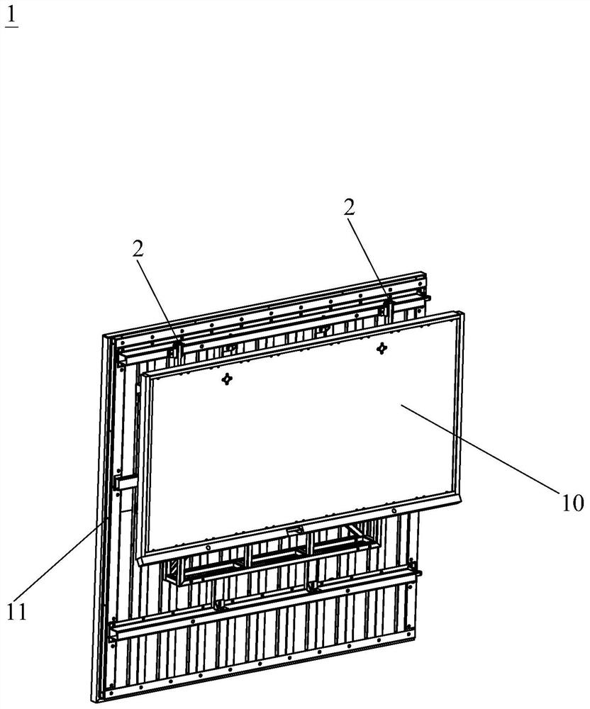
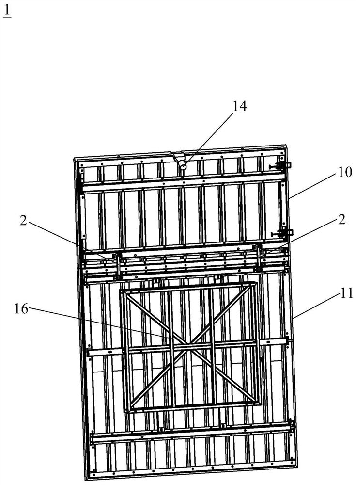
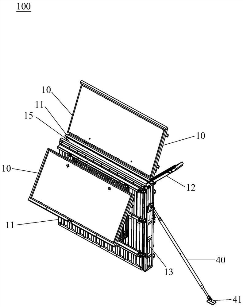
[0022] This embodiment discloses a foldable cast-in-place wall assembly mold, which uses an assembly structure to divide the entire mold into several different parts, specifically, as Figure 1 to Figure 4 , the mold includes an upper mold 10 , a lower mold 11 , an upper side baffle 12 and a lower side baffle 13 . The lower mold 11 is a plate body of a standard size, that is, the lower mold 11 is a standard part, which is the main part of the mould. The upper mold 10 is a plate body of a non-standard size adapted to on-site construction requirements. The upper edge of the upper mold is pivotally connected by a pivot member 2, and by this pivot member 2, the upper mold 10 can rotate 90° relative to the lower mold 11, so that the upper mold...


PUM


Abstract

The invention discloses a foldable cast-in-place wall splicing mold. The foldable cast-in-place wall splicing mold comprises an upper mold body, a lower mold body, an upper side baffle and a lower side baffle; the lower mold body is a plate body of a standard size, the upper mold body is a plate body of a non-standard size matched with site construction requirements, and the lower edge of the upper mold body and the upper edge of the lower mold body are connected in a pivoted mode through a pivoting part, so that the upper mold body can stand above the lower mold body or be stacked with the lower mold body, and a sprue gate is formed in the upper mold body; the lower side baffle is arranged on the side edge of the lower mold body, detachably connected to the lower mold body and used for blocking a pouring cavity formed by the lower mold body; the upper side baffle is arranged on the side edge of the upper mold body, detachably connected to the upper mold body and used for blocking a pouring cavity formed by the upper mold body; and the upper side baffle is connected to the lower side baffle in a pivoted mode. By the adoption of the splicing mold, the mold manufacturing cost can be effectively saved, the mold can be conveniently moved and positioned in the building process, the building difficulty is effectively reduced, and therefore the construction efficiency is improved.

Description

technical field [0001] The invention relates to the technical field of building molds, in particular to a foldable cast-in-place wall assembly mold. Background technique [0002] In the existing building construction technology, there are mainly bricklaying, prefabricated partition wall panels and cast-in-place walls for the construction of interior partition walls. For the bricklaying process, it needs to be built piece by piece with a light body. The construction technical difficulty is low, but the transportation and handling are inconvenient, and the construction period is long, which is not conducive to improving the construction efficiency. For prefabricated partition wall panels, they are directly produced by the factory and spliced ​​at the construction site. Compared with bricklaying technology, the construction efficiency can be effectively improved. However, due to the relatively large size and relatively fixed specifications of prefabricated partition wall panels...

Claims


Application Information

Patent Timeline
IPC IPC(8): E04G11/06E04G11/08E04G9/08
CPCE04G9/083E04G11/06E04G11/08
Inventor 不公告发明人
Owner 广东天凛高新科技有限公司
Why Eureka
Try Eureka