Extension structure of pipeline laying drilling machine

A drilling rig and pipeline technology, applied in the field of pipeline laying equipment, can solve the problems of inability to adjust, the length of the bottom plate is long, and it is inconvenient for flexible transfer.

Active Publication Date: 2021-05-28
CHONGQING UNIVERSITY OF SCIENCE AND TECHNOLOGY
View PDF7 Cites 7 Cited by
  • Summary
  • Abstract
  • Description
  • Claims
  • Application Information

AI Technical Summary

Problems solved by technology

Such a push-pull tube device, the length of the bottom plate is too long and cannot be adjusted, which is not convenient for flexible transfer

Method used


Image

  • Extension structure of pipeline laying drilling machine
  • Extension structure of pipeline laying drilling machine
  • Extension structure of pipeline laying drilling machine

Examples


Embodiment Construction

[0018] The present invention will be further described below in conjunction with embodiment and accompanying drawing.

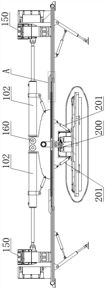
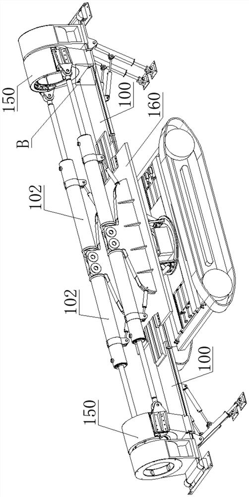
[0019] like Figure 1-6 As shown: an extension structure of a pipeline laying drilling rig, including an installation base plate 100 and a chassis 200, the base plate 200 is located below the installation base plate 100, and the installation base plate 100 is installed on the base plate 200 through the base plate rotating shaft;

[0020] The chassis 200 includes a self-propelled mechanism, the self-propelled mechanism is either a crawler trolley or a wheeled trolley, a horizontal two-dimensional moving mechanism is provided on the self-propelling mechanism, and the horizontal two-dimensional moving mechanism includes mutually perpendicular X To the linear moving device and Y-directed moving device, wherein the moving direction of the X-directed linear moving device can be consistent with the walking direction of the self-propelled mechanism; according to the ...


PUM


Abstract

The invention discloses an extension structure of a pipeline laying drilling machine. The extension structure comprises a mounting bottom plate, wherein a fixed support is arranged on the mounting bottom plate; a pipe pushing telescopic piece is arranged on the fixed support; the pipe pushing telescopic piece is connected with a pipe holding device; the pipe pushing telescopic piece drives the pipe holding device to advance and retreat along the mounting bottom plate; the mounting bottom plate comprises a fixed plate and a movable plate which are in sliding fit with each other; the movable plate slides linearly along the fixed plate, and the sliding direction of the movable plate is consistent with the telescopic direction of the pipe pushing telescopic piece; the movable plate retreats to the fixed plate to form a storage state, and extends out of the fixed plate to form a working state; the fixed support is arranged on the fixed plate; and the pipe holding device is positioned on the movable plate. The extension structure has the remarkable effects that a base for the pipe holding device to walk is arranged in a sliding fit way in a segmented way, so that a short storage state for transportation and transfer can be formed, and the flexibility and the passing ability during transfer and transportation are enhanced; and a long working state for pipe pushing can be formed, so that stable support is provided for the movement of the pipe holding device.

Description

technical field [0001] The invention relates to pipeline laying equipment in the fields of petroleum and natural gas engineering, and in particular to a pipeline laying drilling rig. Background technique [0002] As the pipeline construction enters the peak period, the diameter and steel grade of the pipeline increase, and the construction distance becomes longer. The common non-excavation construction methods such as horizontal directional drilling, pipe jacking, shield tunneling and direct pipe laying methods all adopt intermittent operations. The start-up is faced with a large starting force, and accidents such as broken drill pipes, stuck drill pipes, and collapsed pipes are extremely prone to occur. For the construction of the above complex environments in my country, for example, the Shaanxi-Beijing Fourth Line and the China-Russia East Line all recommend the direct pipe-laying method. The technical advantages of simultaneous completion of reaming drilling and pipe lay...

Claims


Application Information

Patent Timeline
Patent Type & Authority Applications(China)
IPC IPC(8): E21D9/10E21B15/00F16L1/028
CPCE21D9/1093E21B15/003F16L1/028
Inventor 肖鑫源魏秦文祖宝华邓晓刚尹永奇王圣林邓银江
Owner CHONGQING UNIVERSITY OF SCIENCE AND TECHNOLOGY
Why Eureka
Try Eureka