
Bottom water level monitoring device capable of avoiding well wall fracture and automatically alarming

A water level monitoring device and automatic alarm technology, which can be used in measurement devices, mining devices, safety devices, etc., can solve problems such as safety accidents, inability to alarm in time, and complex humidity environment, avoiding instantaneous collapse, increasing escape time, The effect of preventing breakage

Inactive Publication Date: 2021-05-28
高银连
View PDF0 Cites 2 Cited by
  • Summary
  • Abstract
  • Description
  • Claims
  • Application Information

AI Technical Summary

Problems solved by technology

[0005] Aiming at the deficiencies of the prior art, the present invention provides a bottom water level monitoring device that avoids well wall rupture and automatically alarms. It is capable of responding in time when the water inside the bottom seeps downwards and sounds the alarm, and It can limit the flow speed of water, reduce the speed of soil loosening, prevent the rupture of the side wall of the shaft caused by soil loosening, and give the personnel working underground the advantages of more escape time, and solve the problem of bottom water content detection. The sensor is used to detect the water level, but the humidity environment at the bottom of the well is complex, and the sensor is prone to malfunction, making it impossible to give an alarm in time when a dangerous situation occurs, which is likely to cause a larger safety accident.

Method used


Image

  • Bottom water level monitoring device capable of avoiding well wall fracture and automatically alarming
  • Bottom water level monitoring device capable of avoiding well wall fracture and automatically alarming
  • Bottom water level monitoring device capable of avoiding well wall fracture and automatically alarming

Examples

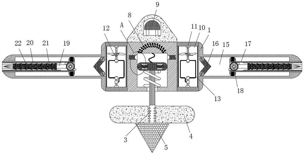
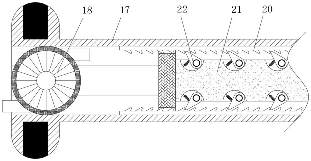

Embodiment Construction

[0025] The following will clearly and completely describe the technical solutions in the embodiments of the present invention with reference to the accompanying drawings in the embodiments of the present invention. Obviously, the described embodiments are only some, not all, embodiments of the present invention. Based on the embodiments of the present invention, all other embodiments obtained by persons of ordinary skill in the art without making creative efforts belong to the protection scope of the present invention.

[0026] see Figure 1-5 , a bottom water level monitoring device that avoids well wall rupture and automatically alarms, comprising a frame 1, a groove is opened in the center of the inside of the frame 1, a slide plate 2 is slidingly connected to the inside of the groove, and the inside of the frame 1 is slidingly connected There is a slide plate 2, grooves are provided on both sides of the slide plate 2, the inside of the groove is slidingly connected with a ...


PUM


Abstract

The invention relates to the technical field of coal mine geological engineering, and discloses a bottom water level monitoring device capable of avoiding well wall fracture and automatically alarming. The bottom water level monitoring device comprises a rack, wherein a sliding plate is slidably connected in the rack, the lower end of the sliding plate is fixedly connected with a pull rod, the surface of the pull rod is fixedly connected with a floating block, a balancing weight is fixedly connected to the lower end of the pull rod, movable blocks are slidably connected to the interior of the sliding plate, metal strips are fixedly connected to the side faces, close to the movable blocks, of the rack, and an electromagnetic rod is fixedly connected to the upper end, close to the sliding plate, of the rack. According to the bottom water level monitoring device, a coil is driven by fan blades to rotate, so that the electromagnetic rod is powered on, the electromagnetic rod attracts the sliding plate at the lower end, the movable blocks are connected with the metal strips on the side faces, an internal circuit is connected, and a buzzer starts to work, and therefore the effects that when water in a well bottom leaks downwards, a response can be made in time, an alarm is pulled, and workers at the well bottom are reminded are achieved.

Description

technical field [0001] The invention relates to the technical field of coal mine geological engineering, in particular to a bottom water level monitoring device which avoids shaft wall rupture and automatically alarms. Background technique [0002] Coal mining needs to open many vertical shafts underground for coal mining and transportation. During the coal mining process, the water head contained in the bottom of the Cenozoic is greatly reduced, which causes compression and deformation of the aquifer and the overlying soil layer, and causes the surface Subsidence, in the process of deformation of the formation, produces a vertical downward additional force on the well wall, causing the shaft wall to rupture. The current bottom water content is generally detected by installing sensors to detect the water level, but the humidity at the bottom of the well is large. Complicated, the sensor is prone to failure, so that it cannot give an alarm in time when a dangerous situation o...

Claims


Application Information

Patent Timeline
IPC IPC(8): E21F17/18E21F17/103E21F11/00G01F23/00G01F23/22
CPCE21F11/00E21F17/103E21F17/18G01F23/0015G01F23/22
Inventor 高银连
Owner 高银连
Learn More