Particle combustion furnace

A combustion furnace and particle technology, applied in the direction of combustion methods, combustion equipment, solid fuel combustion, etc., can solve the problems of insufficient combustion of particle fuel, inability to support combustion, and poor user experience, so as to improve the efficiency and effect of ash falling, Improved fuel efficiency and good combustion-supporting effect

Active Publication Date: 2021-05-28
深圳市艾斯默克科技有限公司
View PDF5 Cites 0 Cited by
  • Summary
  • Abstract
  • Description
  • Claims
  • Application Information

AI Technical Summary

Problems solved by technology

[0002] Existing pellet combustion furnaces, such as barbecue ovens, use a burner that is basically a closed-bottom structure. Air is fed into the combustion-supporting furnace by setting an air inlet on the side wall of the burner. After the pellet fuel is fed into the burner, it will Accumulated on the inner bottom surface of the burner, no matter how low the air inlet is set, it cannot effectively support the combustion of the particulate fuel located on the inner bottom surface of the burner, resulting i

Method used


Image

  • Particle combustion furnace
  • Particle combustion furnace
  • Particle combustion furnace

Examples


Embodiment 1

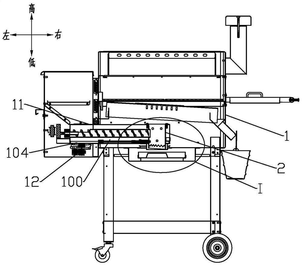
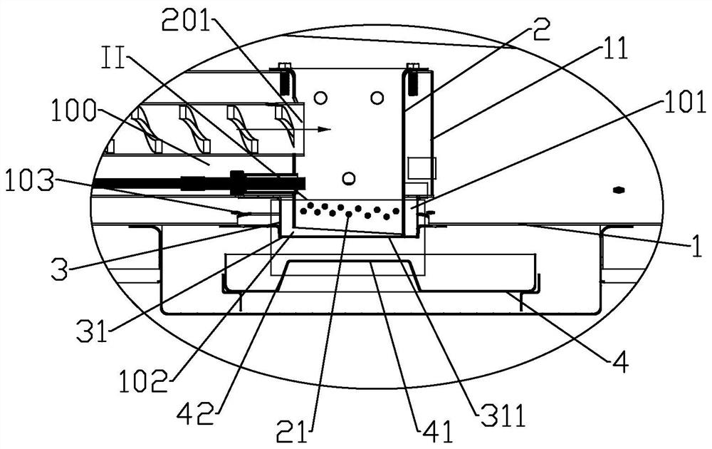
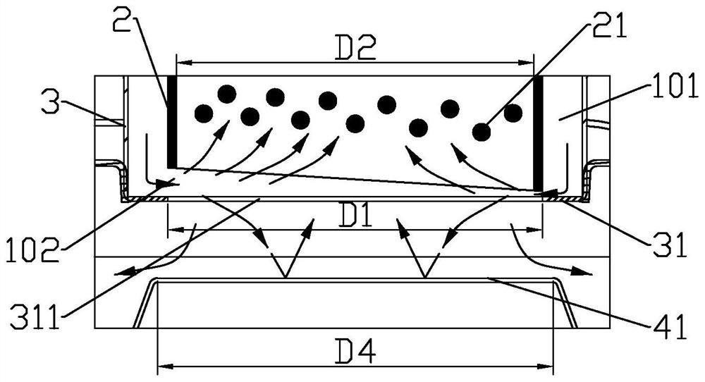
[0022] Such as Figure 1 to Figure 4 As shown, the present invention provides a particle combustion furnace, comprising a furnace body 1, a burner 2 is provided in the furnace body 1, and the furnace body 1 is provided with an air supply channel 100 for feeding air from the outside of the furnace body 1, and the burner 2 The bottom surface is provided with a through-hole for air intake and ash fall, and a fire grate 21 is arranged above the through-hole. The outer wall of the bottom of the burner 2 is provided with an air guide channel 101. The bottom end of the wind channel 101 is provided with an annular windshield 31, and there is an annular air intake gap 102 between the annular windshield 31 and the bottom end of the burner 2. The inner ring of the annular windshield 31 forms a through hole 311, and the bottom of the annular windshield 31 is provided with The rebounding windshield 41 , the rebounding windshield 41 passes through the through hole 311 and faces the through ...

Embodiment 2

[0031] Such as Figure 5 As shown, the inner bottom surface of the ash tray 4 can be directly designed to form a rebound windshield 41.

[0032] For other content not described in this embodiment, reference may be made to the foregoing embodiments.

Embodiment 3

[0034]In addition to setting the ash tray, a water storage tray can also be provided at the bottom of the furnace body. The water storage tray is provided with an upwardly protruding boss, and the top surface of the boss forms a rebound windshield; or, directly use the water surface in the water storage tray Form a rebound windshield. The water storage tray is used to collect the ash, because the pellet fuel burns in the burner, it will generate more heat, the water in the water storage tray is heated, and the evaporation and vaporization of the water are accelerated, and the ash after the pellet fuel burns falls through the through hole. In the process of entering the water storage tray, it will combine with water vapor, which will increase the weight of the ashes and make it easier to fall into the water storage tray without being blown up and flying in the furnace body, which can play a self-cleaning role; water vapor can Combining with the carbon molecules produced during ...


PUM


Abstract

The invention discloses a particle combustion furnace, belongs to the field of combustion equipment, and solves the problem of low combustion efficiency of particle fuel in the prior art. According to the technical scheme, the bottom surface of a combustor is provided with a through hole for air intake and ash falling, a fire grate is arranged above the through hole, and the outer side wall of the bottom of the combustor is provided with an air guide channel; and the top end of the air guide channel is connected with an air supply channel, an annular air baffle is arranged at the bottom end of the air guide channel, an annular air inlet gap is formed between the annular air baffle and the bottom end of the combustor, a through hole is formed in an inner ring of the annular air baffle, and a rebound air baffle is arranged below the annular air baffle and penetrates through the through hole to face the fire grate. The particle combustion furnace is mainly used for promoting the combustion-supporting effect and improving the fuel efficiency of particle fuel.

Description

technical field [0001] The invention relates to combustion equipment, in particular to a particle combustion furnace. Background technique [0002] Existing pellet combustion furnaces, such as barbecue ovens, use a burner that is basically a closed-bottom structure. Air is fed into the combustion-supporting furnace by setting an air inlet on the side wall of the burner. After the pellet fuel is fed into the burner, it will Accumulated on the inner bottom surface of the burner, no matter how low the air inlet is set, it cannot effectively support the combustion of the particulate fuel located on the inner bottom surface of the burner, resulting in insufficient combustion of part of the particulate fuel and cannot be effectively used. Another example is the heating furnace, which will set the grate and air inlet on the bottom of the burner. Since the ashes after burning the pellet fuel will not disperse immediately, they will accumulate on the grate and air inlet after a long ...

Claims


Application Information

Patent Timeline
IPC IPC(8): F23B40/00F23J1/02F23L1/00
CPCF23B40/00F23J1/02F23L1/00
Inventor 郑颖
Owner 深圳市艾斯默克科技有限公司
Why Eureka
Try Eureka