Building blasting pre-dust-fall wall surface spraying equipment

A pre-drop and construction technology, applied in blasting, construction, building maintenance, etc., can solve problems such as narrow spraying range

Pending Publication Date: 2021-05-28
王龙
View PDF0 Cites 0 Cited by
  • Summary
  • Abstract
  • Description
  • Claims
  • Application Information

AI Technical Summary

Problems solved by technology

[0002] In building demolition blasting, in order to reduce dust, the walls of buildings are often sprayed with water. Traditional water spray equipment has a narrow spray range and requires additional power to spray water. Therefore, a building blasting pre- Dust suppression wall spray equipment

Method used


Image

  • Building blasting pre-dust-fall wall surface spraying equipment
  • Building blasting pre-dust-fall wall surface spraying equipment
  • Building blasting pre-dust-fall wall surface spraying equipment

Examples


specific Embodiment approach 1

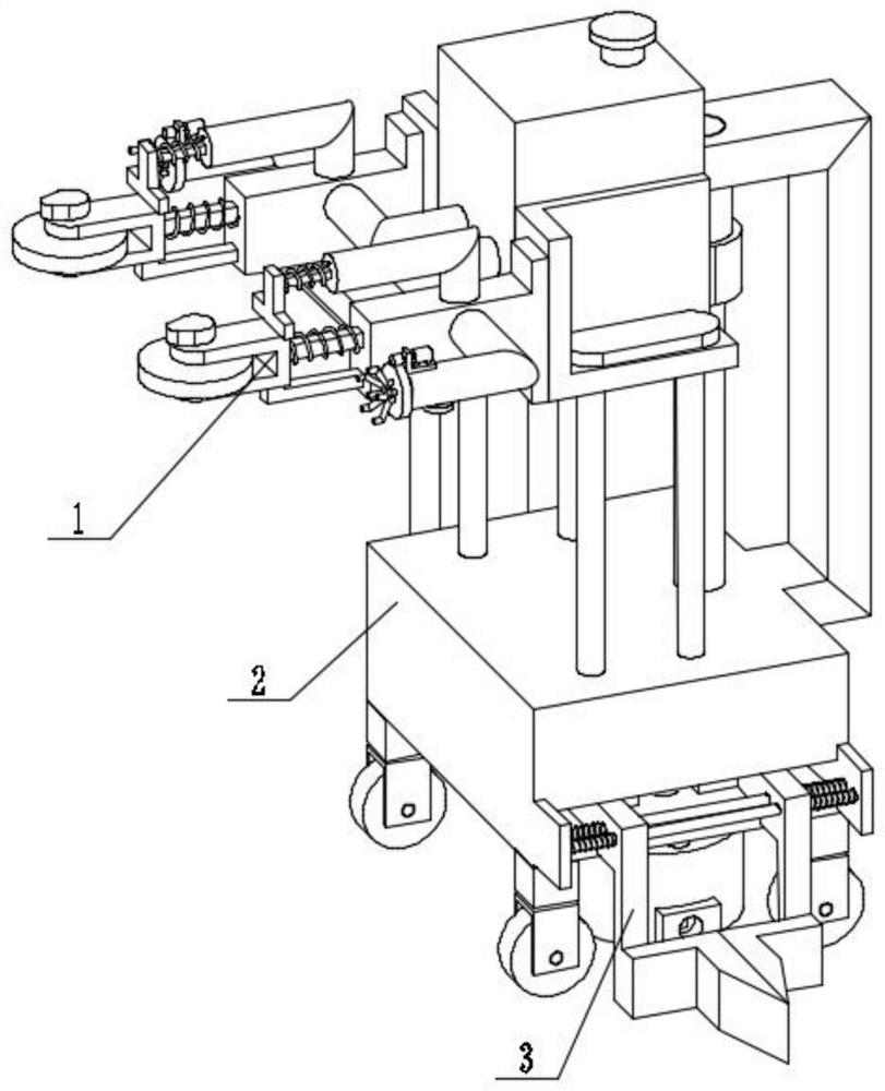
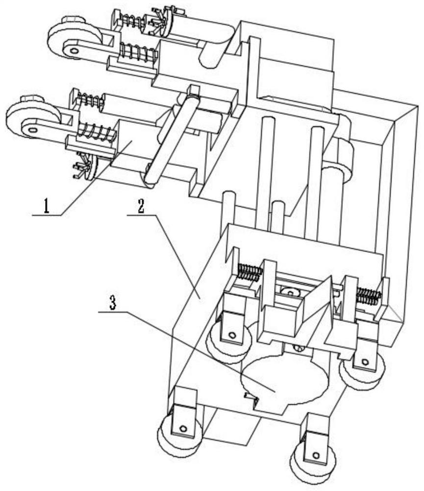
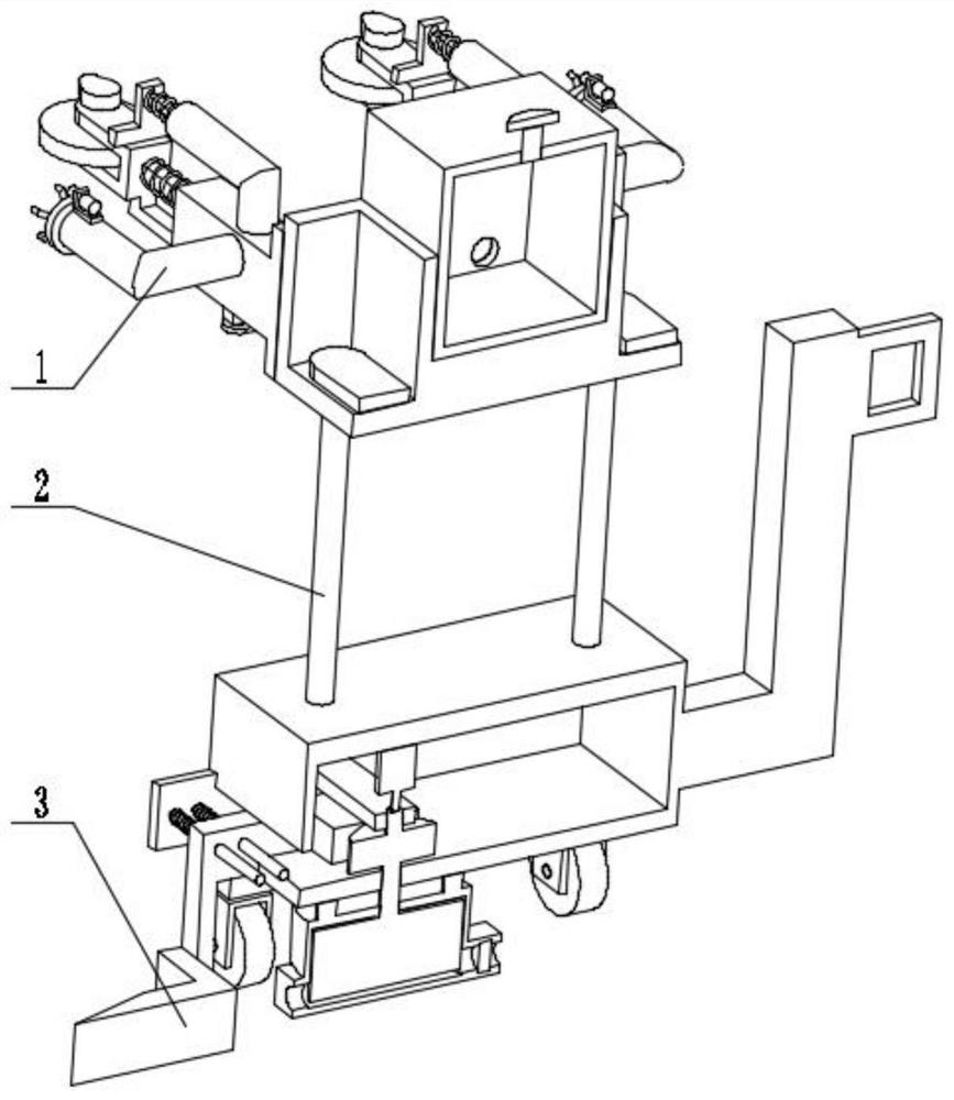
[0032] Combine below figure 1 , figure 2 , image 3 , Figure 4 , Figure 5 , Figure 6 , Figure 7 , Figure 8 , Figure 9 , Figure 10 , Figure 11 , Figure 12 , Figure 13 , Figure 14 , Figure 15 , Figure 16Describe this embodiment, the present invention relates to a kind of spraying equipment, more specifically a kind of construction blasting pre-dedusting wall spraying equipment, including water spraying mechanism 1, vehicle frame mechanism 2, clearing mechanism 3, the equipment can be switched to spraying In the water state, the equipment can use the power of walking to spray water, the equipment can adjust the height of water spray, and the equipment can clear the obstacles in the process of traveling.

[0033] The water spray mechanism 1 is connected to the vehicle frame mechanism 2, and the vehicle frame mechanism 2 is connected to the block clearing mechanism 3.

specific Embodiment approach 2

[0035] Combine below figure 1 , figure 2 , image 3 , Figure 4 , Figure 5 , Figure 6 , Figure 7 , Figure 8 , Figure 9 , Figure 10 , Figure 11 , Figure 12 , Figure 13 , Figure 14 , Figure 15 , Figure 16 Describe this embodiment, this embodiment will further explain embodiment 1, described water spray mechanism 1 comprises water spray seat 1-1, spray pipe 1-2, motor 1-3, gear 1-4, belt ring gear Rotating nozzle 1-5, oblique spray pipe 1-6, straight spray pipe 1-7, sliding seat 1-8, pulley seat 1-9, pulley with shaft 1-10, cam 1-11, cam matching seat 1 -12, square column 1-13, spring 1-14, square column I1-15, spring I1-16, drawing pipe 1-17, water inlet pipe 1-18, water tank 1-19, threaded plug 1-20, connection Plate 1-21, slide valve 1-22, connection chamber 1-23, limit chute 1-24, wedge 1-25, spring II1-26, connecting rod 1-27, slide chamber 1-28, slide valve Moving chamber 1-29, piston 1-30, water outlet one-way valve 1-31, water inlet one-way va...

specific Embodiment approach 3

[0037] Combine below figure 1 , figure 2 , image 3 , Figure 4 , Figure 5 , Figure 6 , Figure 7 , Figure 8 , Figure 9 , Figure 10 , Figure 11 , Figure 12 , Figure 13 , Figure 14 , Figure 15 , Figure 16 Describe this embodiment, this embodiment will further explain the first embodiment, the frame mechanism 2 includes universal wheels 2-1, polished rod 2-2, return spring 2-3, vehicle body 2-4, limit post 2-5, connection limit plate 2-6, movable support platform 2-7, bearing seat 2-8, threaded hole 2-9, lead screw 2-10, chute 2-11, inner bearing seat 2-12, Pushing seat 2-13, shaft coupling 2-14, servo motor 2-15, universal wheel 2-1 links to each other with car body 2-4, polished rod 2-2 links to each other with car body 2-4, return spring 2-3 Set on the polished rod 2-2, the car body 2-4 links to each other with the limit column 2-5, the limit column 2-5 links to each other with the connection limit plate 2-6, and the movable support platform 2-7 lin...


PUM


Abstract

The invention relates to spraying equipment, in particular to building blasting pre-dust-fall wall surface spraying equipment. The equipment comprises a water spraying mechanism, a vehicle frame mechanism and a blockage clearing mechanism, the equipment can be switched to a water spraying state, the equipment can spray water through walking power, the equipment can adjust the water spraying height, the equipment can clear obstacles in the advancing process, the water spraying mechanism is connected with the vehicle frame mechanism, and the vehicle frame mechanism is connected with the blockage clearing mechanism.

Description

technical field [0001] The invention relates to a spraying device, in particular to a wall spraying device for pre-dedusting of building blasting. Background technique [0002] In building demolition blasting, in order to reduce dust, the walls of buildings are often sprayed with water. Traditional water spray equipment has a narrow spray range and requires additional power to spray water. Therefore, a building blasting pre- Dust suppression wall spray equipment. Contents of the invention [0003] The technical problem mainly solved by the present invention is to provide a kind of construction blasting pre-dust reduction wall spray equipment, the equipment can be switched to the water spray state, the equipment can use the power of walking to spray water, the equipment can adjust the spray height, and the equipment can clean the moving obstacles. [0004] In order to solve the above-mentioned technical problems, the present invention relates to a spraying device, more sp...

Claims


Application Information

Patent Timeline
Patent Type & Authority Applications(China)
IPC IPC(8): F42D3/02F42D5/00E04G23/08B01D50/00
CPCF42D3/02F42D5/00E04G23/08B01D50/60
Inventor 王龙
Owner 王龙
Why Eureka
Try Eureka