OPC correction method and OPC correction device

A starting position and line technology, applied in the field of OPC correction method and OPC correction device, can solve the problems of poor OPC correction effect, achieve the effect of avoiding conflicts and improving the effect of OPC correction

Active Publication Date: 2021-05-28
CHANGXIN MEMORY TECH INC
View PDF4 Cites 0 Cited by
  • Summary
  • Abstract
  • Description
  • Claims
  • Application Information

AI Technical Summary

Problems solved by technology

[0006] The invention provides an OPC correction method and an OPC correction device, which are used to solve the problem of poor OPC correction effect in the prior art

Method used


Image

  • OPC correction method and OPC correction device
  • OPC correction method and OPC correction device
  • OPC correction method and OPC correction device

Examples


Embodiment Construction

[0045] The specific implementations of the OPC correction method and the OPC correction device provided by the present invention will be described in detail below in conjunction with the accompanying drawings.

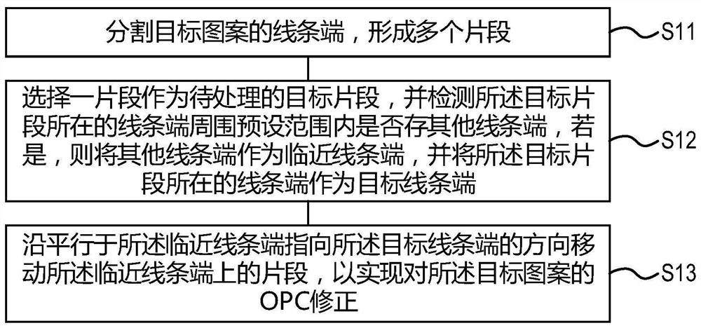
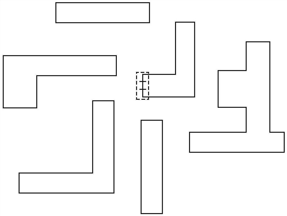
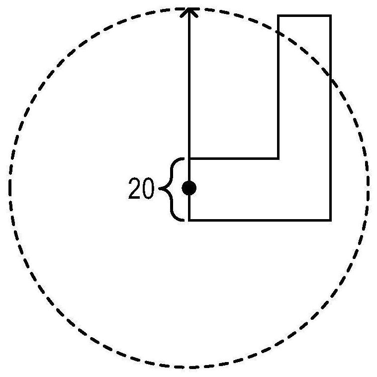
[0046] This specific embodiment provides an OPC correction method, with figure 1 It is a flow chart of the OPC correction method in the specific embodiment of the present invention, with Figures 2A-2D It is a schematic diagram of main steps in the process of performing OPC correction in the specific embodiment of the present invention. Such as figure 1 , Figure 2A-Figure 2D As shown, the OPC correction method provided in this specific embodiment includes the following steps:

[0047] Step S11, dividing the line ends of the target pattern to form multiple segments.

[0048] the following to Figure 2A The structure of the target pattern shown is described as an example. in such as Figure 2A In the target pattern shown, the target pattern has a plurality of mutua...


PUM


Abstract

The invention relates to the technical field of photoetching, in particular to an OPC method and an OPC device. The OPC correction method comprises the following steps: segmenting a line end of a target pattern to form a plurality of segments; selecting one segment as a to-be-processed target segment, detecting whether other line ends exist in a preset range around the line end where the target segment is located, if so, taking the other line ends as adjacent line ends, and taking the line end where the target segment is located as a target line end; and moving the segment on the adjacent line end along a direction parallel to the adjacent line end and pointing to the target line end, so as to realize OPC correction of the target pattern. According to the method, the multiple adjacent line ends in the target pattern can be converged at the same time, the problem that a multi-line-end pattern is prone to conflict in the OPC correction process is solved, and the OPC correction effect is improved.

Description

technical field [0001] The invention relates to the technical field of photolithography, in particular to an OPC correction method and an OPC correction device. Background technique [0002] During the semiconductor lithography process, due to the diffraction effect of ultraviolet light, when the pattern on the mask is projected onto the wafer, the pattern formed on the surface of the wafer is often distorted, resulting in a decrease in the final imaging quality. This phenomenon It is called the optical proximity effect (Optical Proximity Effect, OPE). The pattern distortion on the wafer surface caused by the optical proximity effect is mainly manifested as the shift of the critical dimension (CD) of the line width, the shortening of the end of the line (End Of Line, EOL), and the pattern missing or bridging (Missed Patterns Or Bridging) , Corner rounding (CornerRounding) and other features. [0003] Appropriate modifications are made to the graphics on the reticle to comp...

Claims


Application Information

Patent Timeline
IPC IPC(8): G03F1/36
CPCG03F1/36
Inventor 徐进
Owner CHANGXIN MEMORY TECH INC
Why Eureka
Try Eureka