Fixing support of PLC (programmable logic controller)

A technology of programming controller and fixing bracket, applied in the direction of program control, electrical program control, digital control, etc., can solve the problems of parts detachment, strong inertial force and centrifugal force of the fixed bracket, etc., and achieve the effect of increasing friction.

Inactive Publication Date: 2021-05-28
李德水
View PDF6 Cites 0 Cited by
  • Summary
  • Abstract
  • Description
  • Claims
  • Application Information

AI Technical Summary

Problems solved by technology

[0003] Based on the discovery of the inventors above, the existing methods mainly have the following disadvantages, such as: when using equipment to clamp parts with relatively smooth surfaces, since the clamping end face of the fixed bracket is fixed by rubber rolling clamping, the The fast-rotating fixed bracket under the control of the editing program will generate strong inertial force and centrifugal force, so that the parts wrapped and fixed by rubber can easily break away from the engagement state of the fixed bracket under the centrifugal force.

Method used


Image

  • Fixing support of PLC (programmable logic controller)
  • Fixing support of PLC (programmable logic controller)
  • Fixing support of PLC (programmable logic controller)

Examples


Embodiment 1

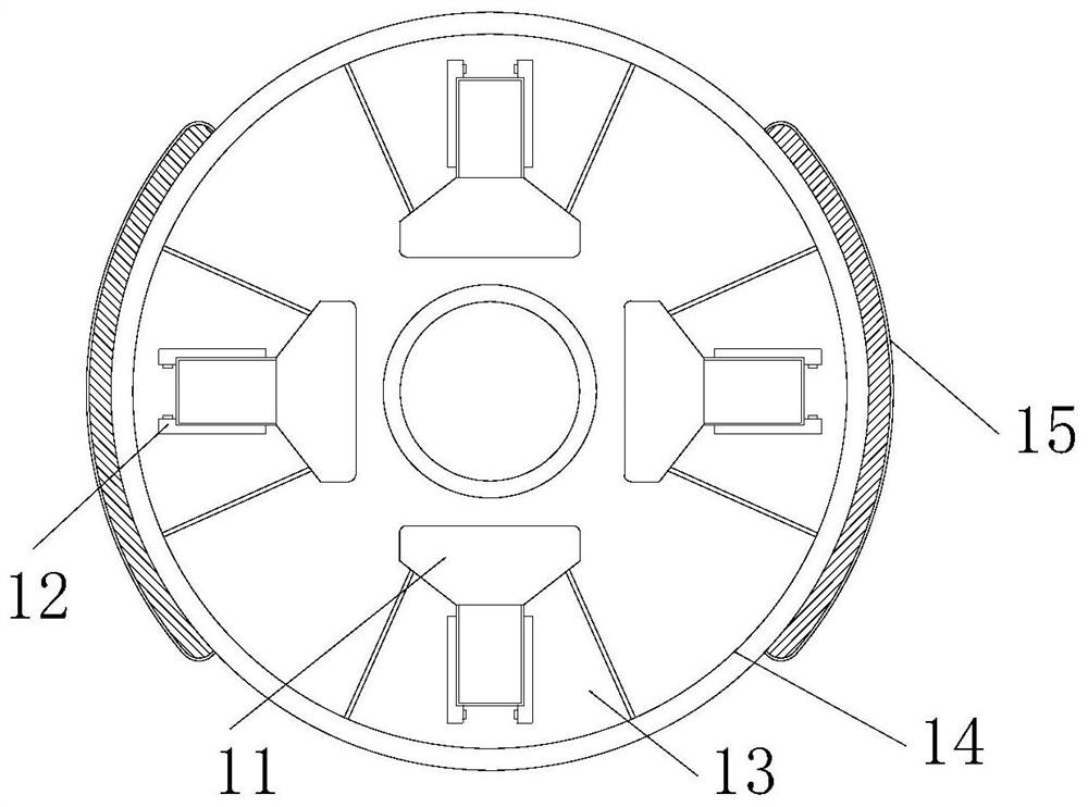
[0025] as attached figure 1 to attach Figure 5 Shown:

[0026] The invention provides a fixed bracket for a PLC programmable controller, the structure of which includes a clamping device 1, a power disc 2, and a control base 3. The clamping device 1 is embedded and installed on the outer end surface of the power disc 2. The power The inlaid block on the lower end surface of the disc 2 is engaged with the control base 3, and the outer end surface of the control base 3 is connected to the clamping device 1; the clamping device 1 includes a clamping mechanism 11, a chute 12, an adjustment block 13, The fixed plate 14 and the embedded connecting strip 15, the clamping mechanism 11 is movably engaged with the inner end surface of the chute 12, the chute 12 is inlaid on the outer end surface of the adjustment block 13, and the adjustment block 13 is evenly embedded and installed On the upper surface of the clamping device 1 , the outer end surface of the fixed plate 14 is attache...

Embodiment 2

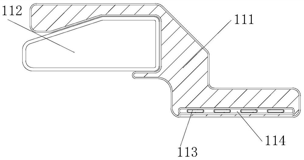
[0033] as attached Figure 6 to attach Figure 7 Shown:

[0034]Wherein, the filling ball 221 includes a wrapping piece 211, a rectangular cavity 212, an adsorption mechanism 213, a rubber ball 214, and a half-arc piece 215. The cavity 212 is evenly arranged on the outer end surface of the wrapping sheet 211, the outer end surface of the adsorption mechanism 213 is attached to the rectangular cavity 212, the inner end surface of the rubber ball 214 is attached to the half-arc sheet 215, and the half-arc sheet 215 Located on the right side of the wrapping sheet 211 , the rubber ball 214 adopts a sandwich hollow design, which can cause corresponding deformation when being squeezed, and then expand outward along the rectangular cavity 212 .

[0035] Wherein, the adsorption mechanism 213 includes a bonding layer 131, an embedding plate 132, an air permeation hole 133, an arc block 134, and a rubber sheet 135. 132 is embedded with a rubber sheet 135 on the upper end surface. The...


PUM


Abstract

The invention discloses a fixing support of PLC (programmable logic controller). The fixing support structurally comprises a clamping device, a power disc and a control base; the clamping device is fixedly mounted on the outer side end face of the power disc in an embedded mode, an embedded block on the lower end face of the power disc is connected with the control base in a clamped mode, and the outer side end face of the control base is connected with the clamping device in an attached mode; a hollow block is squeezed into a buffer groove under full air, a full ball is also made of a rubber material and can expand outwards during squeezing to wrap an object as much as possible, the object is covered by arrayed locking blocks, the surface friction force between the object and a clamping mechanism is increased through a wrapping mechanism, and it can be effectively guaranteed that in the rotating process, it is avoided that articles fall off due to the weak fixing capacity.

Description

technical field [0001] The invention belongs to the field of processing equipment containing a PLC programmable controller, and more specifically relates to a fixed bracket for a PLC programmable controller. Background technique [0002] The programmable control fixed bracket is a kind of key programming with actual use. In the process of processing, the programmed fixed bracket is used in cooperation with the processing equipment to process the clamped parts. It is mainly used in the processing field. [0003] Based on the above inventors' discovery, the existing methods mainly have the following disadvantages, such as: when using equipment to clamp parts with smooth surfaces, since the clamping end face of the fixed bracket is fixed by rubber rolling clamping, the The rapidly rotating fixed bracket under the control of the editing program will generate strong inertial force and centrifugal force, so that the parts wrapped and fixed by rubber can easily break away from the ...

Claims


Application Information

Patent Timeline
Patent Type & Authority Applications(China)
IPC IPC(8): G05B19/19
CPCG05B19/19G05B2219/35349
Inventor 刘生玉
Owner 李德水
Why Eureka
Try Eureka