

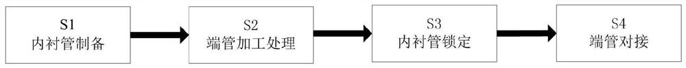
Electric power insulator manufacturing and forming process
A molding process and insulator technology, which is applied in the direction of insulators, circuits, electrical components, etc., can solve the problems of axial displacement, poor position adjustment accuracy of bushing and inner liner, and low efficiency of insulator insertion, so as to increase applicability , increase the connection accuracy, increase the effect of the connection effect
- Summary
- Abstract
- Description
- Claims
- Application Information
AI Technical Summary
Problems solved by technology
Method used
Image

Examples
Embodiment Construction
[0034] The embodiments of the present invention will be described in detail below with reference to the accompanying drawings, but the present invention can be implemented in many different ways defined and covered by the claims.
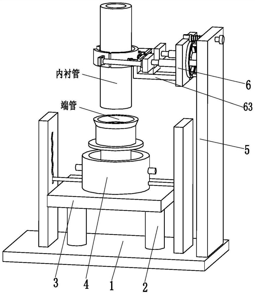
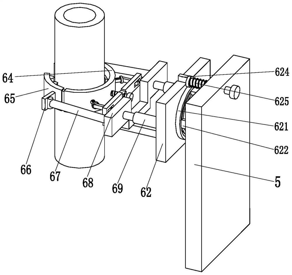
[0035] Such as Figure 2-7 As shown, a power insulator manufacturing and molding process, the power insulator manufacturing and molding process uses the following insulator forming device, the insulator forming device includes a bottom plate 1, a jacking cylinder 2, a jacking support plate 3, a docking mechanism 4, and a clamping vertical plate 5 And the clamping mechanism 6, the top of the bottom plate 1 is equipped with a top extension support plate 3 through the top extension cylinder 2, a docking mechanism 4 is installed on the upper side of the middle part of the top extension support plate 3, and the top of the outer end of the bottom plate 1 The clamping vertical plate 5 is installed, and the clamping mechanism 6 is installed on the side of t...
PUM
 Abstract
Description
Claims
Application Information