Elastic contact structure of socket contact piece

An elastic contact and contact piece technology, applied in the direction of contact parts, etc., can solve the problems of small contact pressure between the moving contact piece and the static contact piece, limited movement stroke of the moving contact piece of the rotating block, and easy occurrence of electric sparks, etc., to achieve increased swing The effect of increasing the range, increasing the elastic activity margin, and improving the operating feel

Pending Publication Date: 2021-05-28
JIANGSU GENERAL PROTECHT
View PDF0 Cites 0 Cited by
  • Summary
  • Abstract
  • Description
  • Claims
  • Application Information

AI Technical Summary

Problems solved by technology

[0003] However, in the existing sockets, the movement stroke of the rotating block and the moving contact piece is limited, and the static contact piece is generally rigidly installed, resulting in a rigid collision between the moving contact piece and the static contact piece, prone to electric sparks, and the moving contact piece is prone to fatigue After a long time of use, the contact pressure between the moving contact piece and the static contact piece becomes smaller and smaller, and in serious cases, the problem of power failure will occur

Method used


Image

  • Elastic contact structure of socket contact piece
  • Elastic contact structure of socket contact piece
  • Elastic contact structure of socket contact piece

Examples


Embodiment Construction

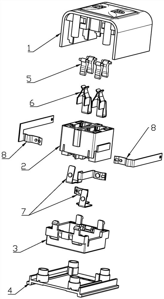
[0020] Such as figure 1 As shown, it is a kind of anti-electric shock safety socket, which includes an upper cover 1, a middle frame 2, a rear cover 3 and a lower cover 4. The upper cover 1 is provided with jacks for inserting the blades of the plug, and each jack is two Each side is pivotally connected with a rotary block 5, the middle frame 2 is fixed with an insertion grip 6, a movable contact piece 7 and a static contact piece 8 are fixed between the rear cover 3 and the middle frame 2, and the lower cover 4 and the The upper cover 1 is correspondingly closed.

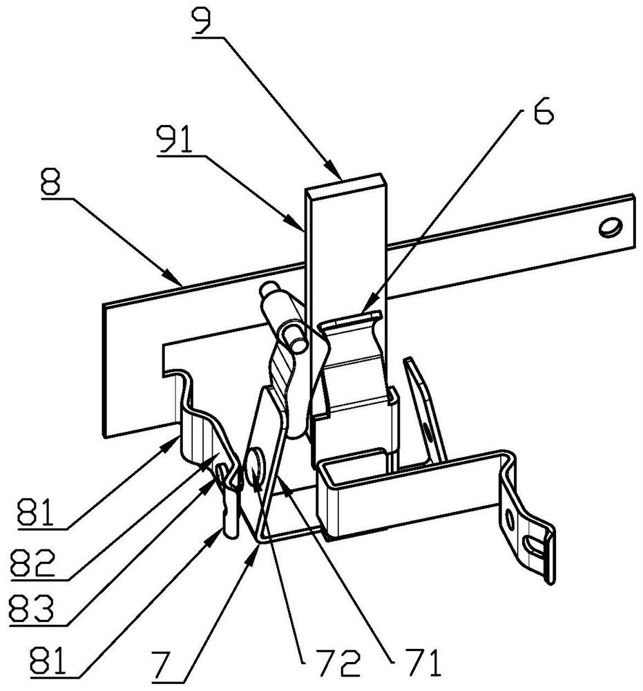
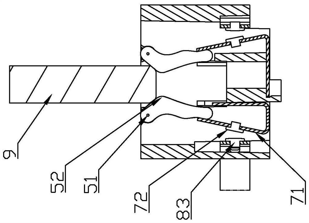
[0021] Such as Figure 2-Figure 4 As shown, the inserting piece 9 has two planar parts and two ridges 91 arranged oppositely, the inserting handle 6 can clamp the two planar parts of the inserting piece 9, and each of the inserting pieces 9 A said rotary block 5 is arranged on the outside of each ridge 91; the rotary block 5 is C-shaped as a whole, and its upper end is pivotally connected to the upper cover 1 thr...


PUM


Abstract

The invention provides an elastic contact structure of a socket contact piece. The elastic contact structure is characterized in that a rotating block is arranged on the outer side of a ridge part of an insertion piece; a movable contact piece is arranged on the outer side of the rotating block; a static contact piece is arranged on the outer side of the movable contact piece; the upper end of the rotating block is pivoted and fixed; a convex stress part is arranged on one the portion, located at one side close to the ridge part and between an upper end and a lower end, of the rotating block; the lower end of the rotating block extends out towards a direction far away from the ridge part; the movable contact piece is a metal piece body and is provided with an elastic arm which is formed by bending and extending a horizontal bottom upwards; the top end of the elastic arm abuts against one side, far away from the ridge part, of the lower end of the rotating block; a movable contact is arranged between the upper end and the lower end of the elastic arm; and the static contact piece is a metal piece body and is provided with two supporting legs which are arranged in a separated mode, a suspension part is arranged between the two supporting legs, and a static contact is arranged on the suspension part. According to the invention, elastic contact between the contact pieces can be realized, so rigid impact is avoided, the operation hand feeling of insertion of the insertion piece can be improved, and the service life of the socket is prolonged.

Description

technical field [0001] The present invention relates to contact structures of contacts in sockets. Background technique [0002] The socket is a device for inserting the plug to take electricity. It has a slot for inserting the insert of the plug. A rotating block, a moving contact piece and a static contact piece are arranged in the slot. When the inserting piece is inserted, the rotating block is driven by the inserting piece. And rotation occurs, and the rotating block stirs the movable contact again, so that the movable contact forms an electrical connection with the static contact, to complete the power-taking work. [0003] However, in the existing sockets, the movement stroke of the rotating block and the moving contact piece is limited, and the static contact piece is generally rigidly installed, resulting in a rigid collision between the moving contact piece and the static contact piece, prone to electric sparks, and the moving contact piece is prone to fatigue , A...

Claims


Application Information

Patent Timeline
Patent Type & Authority Applications(China)
IPC IPC(8): H01R13/15H01R13/02
CPCH01R13/02H01R13/15
Inventor 王祥严华陈彬
Owner JIANGSU GENERAL PROTECHT
Why Eureka
Try Eureka