Card edge connector combination and card locking mechanism thereof

A card edge connector and card locking technology, which is applied in the connection, the parts of the connecting device, the protective grounding/shielding device of the connecting parts, etc. Easy to operate and avoid damage to the effect of the electronic card

Pending Publication Date: 2021-05-28
FOXCONN (KUNSHAN) COMPUTER CONNECTOR CO LTD +1
View PDF1 Cites 2 Cited by
  • Summary
  • Abstract
  • Description
  • Claims
  • Application Information

AI Technical Summary

Problems solved by technology

However, the buckle mechanism relies on its own elastic lock to lock the electronic card, so it is inconvenient to return the card, and it cannot hold the electronic card stably.

Method used


Image

  • Card edge connector combination and card locking mechanism thereof
  • Card edge connector combination and card locking mechanism thereof
  • Card edge connector combination and card locking mechanism thereof

Examples


Embodiment Construction

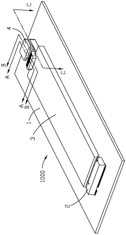
[0025] see Figure 1 to Figure 14 , the present invention provides a card edge connector assembly 1000, which includes a circuit board 1, a card edge connector 2 mounted on the circuit board, and a locking mechanism 4 fixed on the circuit board 1 for locking an electronic card 3 . The circuit board 1 is provided with a key-shaped opening 11 . In this embodiment, one end of the electronic card 3 is provided with upper, middle and lower arc-shaped notches, which are respectively defined as a first notch 31 , a second notch 32 and a third notch 33 . The radius of the second notch 32 in the middle is smaller than the radii of the first and third notches 31 , 33 , thereby forming a middle support plate 34 , and the second notch 32 is formed on the middle support plate 34 .

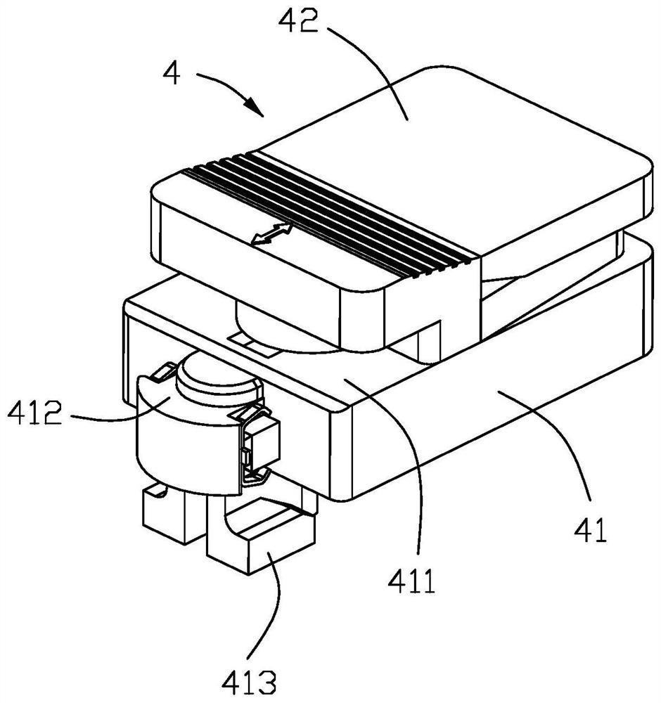
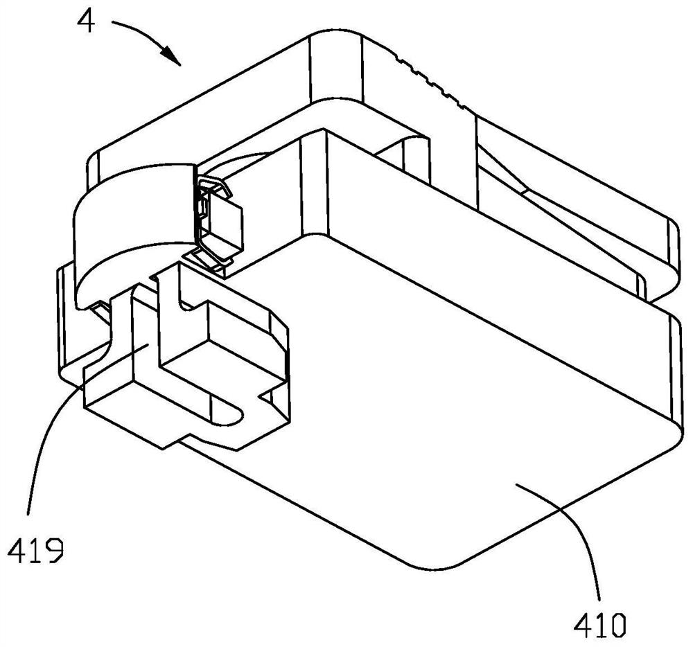
[0026] ginseng Figure 2 to Figure 5 , the locking mechanism 4 is fixed in the opening 11 of the above-mentioned circuit board 1 . The locking mechanism 4 includes a base 41 and a locking member 42 clamped ...


PUM


Abstract

A card edge connector combination comprises a circuit board, a card edge connector installed on the circuit board and a card locking mechanism which is fixed on the circuit board and used for locking an electronic card, the circuit board is provided with a key-shaped opening, the card locking mechanism comprises a base and a locking piece which is clamped on the base and can slide back and forth, the base comprises a tower part formed by extending upwards and a mounting part formed by extending downwards, a sliding groove is formed in the tower part in a concave mode, and the locking piece comprises a clamping and abutting part and a pair of elastic arms clamped in the sliding groove; and the mounting part is detachably mounted at the opening. Through the arrangement, the card locking mechanism can be installed on the circuit board and lock the electronic card without assistance of tools, and the position of the card locking mechanism can be flexibly adjusted.

Description

【Technical field】 [0001] The invention relates to a card edge connector assembly, in particular to a card edge connector assembly with a locking mechanism. 【Background technique】 [0002] No. TWM576624U of China Taiwan's new patent announcement discloses a spacer column, which includes a base, the bottom surface of the base is provided with a slide block for connecting the first plate hole of the first plate, and the bottom wall of the slide block is connected to the first plate hole. The outer peripheral surface between the bases has a U-shaped chute, the first plate hole includes a perforation for the bottom wall to pass through, and the perforation is laterally connected to a communication groove for the chute to slide and position, A hollow inner wall in the chute is opposite to at least one side edge corresponding to the communication groove, and at least one buckling mechanism is provided, and each of the buckling mechanisms includes a buckle tenon and a buckle groove ...

Claims


Application Information

Patent Timeline
Patent Type & Authority Applications(China)
IPC IPC(8): H01R13/639H01R13/648H01R12/72H01R12/73
CPCH01R13/639H01R13/648H01R12/721H01R12/73H05K7/1417G06F1/185G06F1/183H05K7/12
Inventor 徐光磊李庄星赵志斌唐文军
Owner FOXCONN (KUNSHAN) COMPUTER CONNECTOR CO LTD
Why Eureka
Try Eureka