Face detection chip for face recognition device
A technology of face recognition and face detection, which is applied in the direction of semiconductor/solid-state device parts, semiconductor devices, electrical components, etc., and can solve the problem of no bending and breaking of pins, no external impact protection, no flexible adjustment of installation position, etc. problem, to achieve the effect of protection against bending and fracture, stable installation, and flexible adjustment of installation position
- Summary
- Abstract
- Description
- Claims
- Application Information
AI Technical Summary
Problems solved by technology
Method used
Image
Examples
Embodiment 1
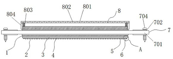
[0030] Example 1: See Figure 1-6 , a face detection chip for a face recognition device, comprising a semiconductor chip 1, a plurality of groups of metal pins 2 are uniformly arranged on the bottom of the semiconductor chip 1, and a pin protection structure is arranged on the bottom of the semiconductor chip 1;
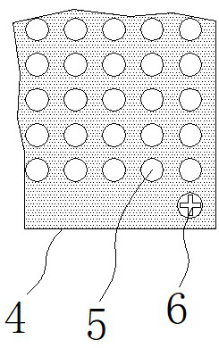
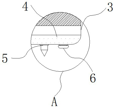
[0031] see Figure 1-6 A face detection chip for a face recognition device also includes a stitch protection structure, the stitch protection structure includes a hard substrate 3, the hard substrate 3 is fixedly connected to the bottom end of the semiconductor chip 1, and the bottom end of the hard substrate 3 is fixedly connected to a The silicone cushion 4, the hard substrate 3 and the silicone cushion 4 are respectively provided with multiple groups of pinholes 5, and the two sides of the low end of the silicone cushion 4 are respectively fixedly connected with fixing bolts 6;
[0032] Silicone cushions 4 are arranged at equal intervals;
[0033] The inner diam...
Embodiment 2
[0036] Embodiment 2: The outside of the semiconductor chip 1 is provided with an adjustable mounting structure 7. The adjustable mounting structure 7 is composed of a mounting plate 701, a mounting screw groove 702, an anti-wear washer 703 and a mounting screw 704. The mounting plate 701 is sleeved on the semiconductor chip. 1, the insides of both sides of the mounting plate 701 are respectively provided with mounting screw grooves 702, the inside of the mounting screw grooves 702 is provided with anti-wear washers 703, and the inside of the mounting screw grooves 702 is inserted with mounting screws 704;
[0037] The outer diameter of the anti-wear washer 703 is consistent with the inner diameter of the mounting screw groove 702;
[0038] The mounting screw grooves 702 are distributed symmetrically about the vertical center line of the mounting plate 701;
[0039] Specifically, such as figure 1 , Figure 4 and Figure 5 As shown, the mounting plate 701 serves as the base o...
Embodiment 3
[0040] Embodiment 3: The top of the semiconductor chip 1 is provided with a top protective structure 8, the top protective structure 8 is composed of a protective net 801, a cooling hole 802, a silica gel column 803 and a side frame 804, the protective net 801 is arranged on the top of the semiconductor chip 1, and the protection The inside of the net 801 is uniformly provided with cooling holes 802, the two sides of the bottom of the protective net 801 are respectively fixedly connected with silica gel posts 803, and the bottom of the protective net 801 is fixedly connected with side frames 804;
[0041] Silica gel columns 803 are symmetrically distributed about the vertical centerline of the protective net 801;
[0042] Specifically, such as figure 1 and Figure 6As shown, when the impact on the top comes, the protective net 801 directly bears the pressure and transmits the impact force to the silica gel column 803, and the soft silica gel column 803 shrinks to reduce the f...
PUM
 Abstract
Description
Claims
Application Information
 - R&D
- Intellectual Property
- Life Sciences
- Materials
- Tech Scout
- Unparalleled Data Quality
- Higher Quality Content
- 60% Fewer Hallucinations
Browse by: Latest US Patents, China's latest patents, Technical Efficacy Thesaurus, Application Domain, Technology Topic, Popular Technical Reports.
© 2025 PatSnap. All rights reserved.Legal|Privacy policy|Modern Slavery Act Transparency Statement|Sitemap|About US| Contact US: help@patsnap.com


