Live-line installation method for low-voltage detachable lightning arrester

An installation method and lightning arrester technology are applied in the field of lightning arresters to achieve the effects of improving stability, facilitating installation, and improving emergency repair effects

Active Publication Date: 2021-12-24
国网安徽省电力有限公司潜山市供电公司 +2
View PDF6 Cites 0 Cited by
  • Summary
  • Abstract
  • Description
  • Claims
  • Application Information

AI Technical Summary

Problems solved by technology

[0005] The purpose of the present invention is to provide an anti-clogging self-reducing microporous aerator and its use method, which can solve the existing problems

Method used


Image

  • Live-line installation method for low-voltage detachable lightning arrester
  • Live-line installation method for low-voltage detachable lightning arrester
  • Live-line installation method for low-voltage detachable lightning arrester

Examples


Embodiment 1

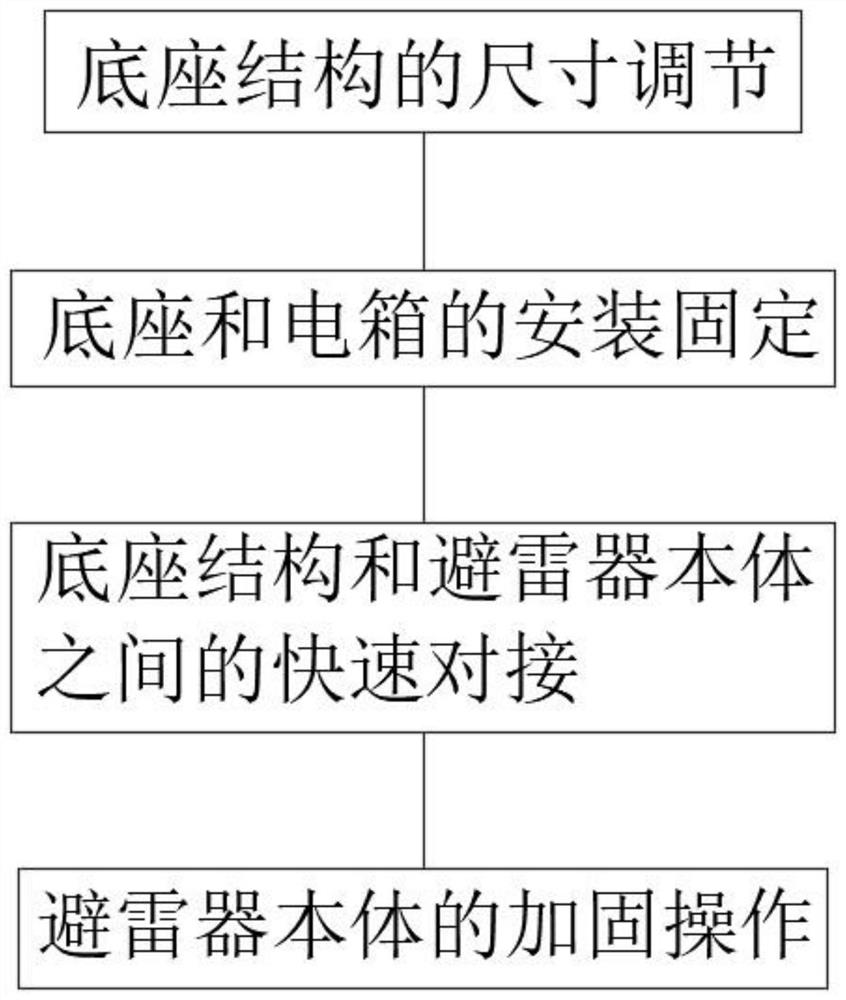
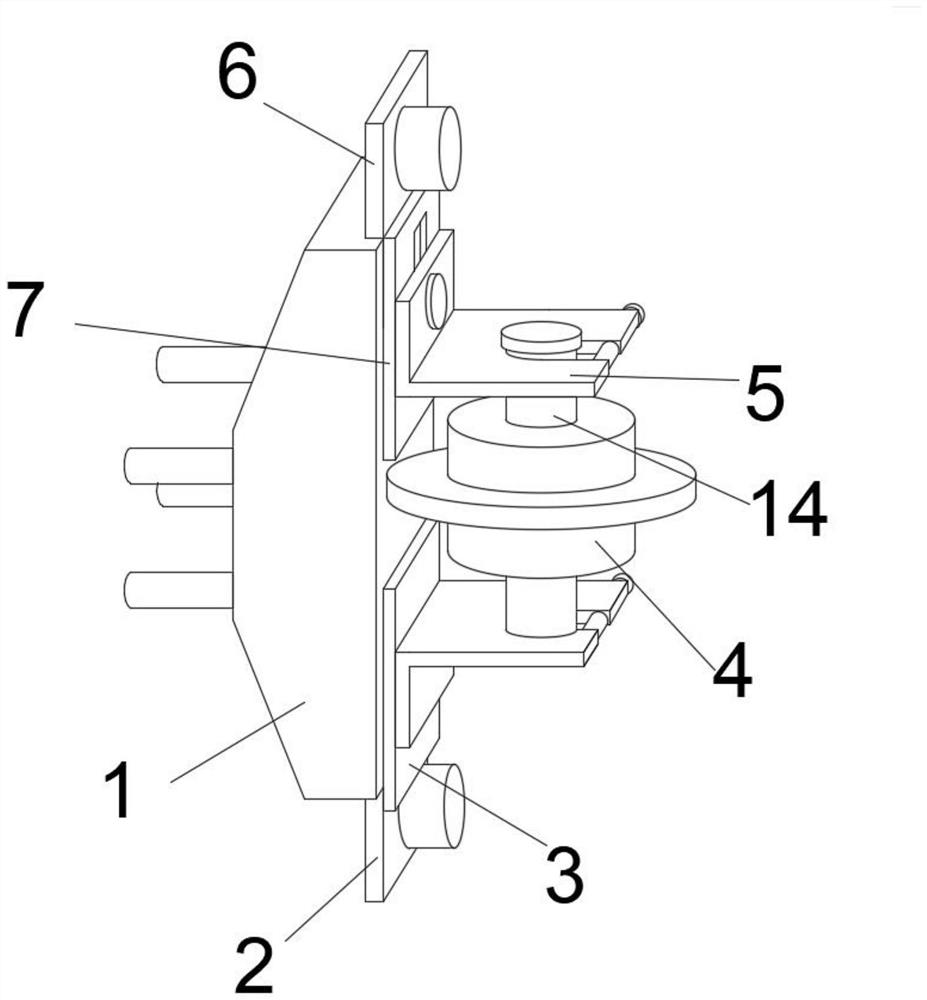
[0041] When the L-shaped card holder 5 is installed, the lifting blocks 10 at the rear ends of the two groups of L-shaped card holders 5 are respectively stuck in the lifting chute 12 of the second card board 7 and the first card board 3, and the L-shaped card is pulled longitudinally. seat 5, so that the lifting block 10 moves in the lifting chute 12, thereby adjusting the distance between the two groups of L-shaped card seats 5, and utilizing the adjustment of the distance between the two groups of L-shaped card seats 5, so that the two groups of L-shaped card seats Arrester bodies 4 of different lengths can be used between the decks 5 .

[0042] When the second clamping plate 7 and the first clamping plate 3 are installed, by clamping the second clamping plate 7 and the first clamping plate 3 in the connecting plate slot 19 of the ceramic base 1, the second clamping plate is screwed together by bolts. 7. The first clamping plate 3 and the ceramic base 1 are fixed, the inner...

Embodiment 2

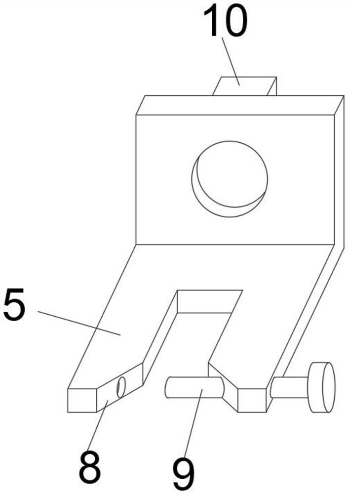
[0045] When the lightning arrester body 4 is docked and installed, the elastic clip rods 14 at both ends of the lightning arrester body 4 are respectively stuck in the docking card slot 8 of the L-shaped card base 5, and the second card is inserted into the docking card slot 8 of the L-shaped card base 5. Bolt 9 is used to limit and fix the elastic clip bar 14. The other end of the docking slot 8 is an inclined plane structure. The middle position of the rear end of the L-shaped card seat 5 is equipped with a lifting block 10 for lifting and lowering. The second clamping plate 7 and the side of the first clamping plate 3 are Z-shaped structures, and one end of the second clamping plate 7 and the first clamping plate 3 is provided with a butt joint nozzle 13 .

[0046] Elastic clip bar 14 when in use, the lifting push rod 16 of elastic clip bar 14 is stuck on the surface of L-shaped deck 5, it is fixed, and the side of the second clip 7 and the first clip 3 is provided with Lif...

Embodiment 3

[0048] When the lifting jack 16 is in use, the spring buckle 17 is used to pull down the lifting jack 16, so that the lifting jack 16 and the elastic clamping rod 14 produce an elastic clamping structure, and cooperate with the washer at the bottom of the lifting jack 16 to carry out the L-shaped clamping seat 5 Clamping and fixing, the first clamping plate 3 is docked and fixed by the docking bayonet 13 and the first wire plate 2, and the inner side of one end of the elastic clamp rod 14 is movable with a lifting jack 16, and the elastic clamping rod 14 and the lifting jack 16 are Through the elastic connection of the spring buckle 17, two sets of limit rings 15 are installed at the lower side of the lift rod 16.

[0049] When the moving slider 18 is in use, the moving slider 18 is pulled by the transverse chute 20 of the arrester body 4, so that the moving slider 18 moves at the rectangular notch 21, thereby adjusting the distance between the two groups of moving sliders 18, ...


PUM


Abstract

The invention discloses a live-line installation method for a low-voltage detachable lightning arrester. The method comprises the following steps of 1, adjusting the distance between two groups of L-shaped clamping seats according to the length of a lightning arrester body; 2, after the butt joint position of a movable sliding buckle is adjusted, under the condition that an electric box is powered on, fixing a ceramic base into the electric box through bolts; 3, through the butt joint clamping grooves of the L-shaped clamping seats, and utilizing the elastic clamping rods at the two ends of the lightning arrester body toclamp the lightning arrester body between the two groups of L-shaped clamping seats, so that the time required for mounting the detachable lightning arrester is shortened. Meanwhile, the stability of the lightning arrester after mounting can be improved by utilizing the arrangement of the second clamping bolts, and an inclined surface structure at one ends of the butt joint clamping grooves can effectively reduce the resistance of the detachable lightning arrester during quick butt joint, so that the detachable lightning arrester is convenient to mount. The mounting method can be used for quickly dismounting and mounting the low-voltage detachable lightning arrester, and the emergency repair effect of the low-voltage detachable lightning arrester is improved.

Description

technical field [0001] The invention belongs to the technical field of lightning arresters, in particular to a live installation method of a low-voltage detachable lightning arrester. Background technique [0002] The low-voltage detachable arrester combines the working principle of the 10 kV detachable arrester, and the low-voltage arrester can be removed for maintenance when the system is not powered off, reducing the power outage time required for the maintenance of the arrester, greatly improving the reliability of power supply and equipment safety and reliability Improve the operation rate and use technical means to improve the service level of high-quality power supply. [0003] Patent document CN203659559U discloses a DC pole line arrester, which includes four arrester elements connected in series, a first voltage equalizing ring assembly and a second voltage equalizing ring assembly; the four arrester elements are respectively the first arrester elements connected in...

Claims


Application Information

Patent Timeline
Patent Type & Authority Applications(China)
IPC IPC(8): H02G13/00
CPCH02G13/80
Inventor 方新华陈徐胜郭伟斌黄承霞汪勇肖国强徐晓斌聂宏智徐幸中
Owner 国网安徽省电力有限公司潜山市供电公司
Why Eureka
Try Eureka