
Ultrasonic cleaning machine for machining energy-saving corrosion-resistant ceramic shaft sleeve

An ultrasonic and corrosion-resistant technology is applied in the field of energy-saving and corrosion-resistant ceramic bushing processing ultrasonic cleaners, which can solve problems such as inconvenient operation for workers, damage to ceramic bushings, extrusion stacking, etc., so as to improve the air-drying effect and increase the blowing area , the effect of improving production efficiency

Pending Publication Date: 2021-06-01
上海晶石陶瓷有限公司
View PDF11 Cites 0 Cited by
  • Summary
  • Abstract
  • Description
  • Claims
  • Application Information

AI Technical Summary

Problems solved by technology

[0004] The purpose of the present invention is to provide an energy-saving ultrasonic cleaning machine for processing corrosion-resistant ceramic bushings, to solve the above-mentioned background technology when processing and cleaning corrosion-resistant ceramic bushings. Due to the particularity of the ceramic bushing structure, the When cleaning the inside of the cleaning box, it is easy to squeeze and stack, resulting in damage to the ceramic bushing. After lifting and cleaning, the cleaning fluid attached to the surface of the ceramic bushing will affect the subsequent processing, which is not convenient for workers to operate.

Method used


Image

  • Ultrasonic cleaning machine for machining energy-saving corrosion-resistant ceramic shaft sleeve
  • Ultrasonic cleaning machine for machining energy-saving corrosion-resistant ceramic shaft sleeve
  • Ultrasonic cleaning machine for machining energy-saving corrosion-resistant ceramic shaft sleeve

Examples


Embodiment Construction

[0020] The following will clearly and completely describe the technical solutions in the embodiments of the present invention with reference to the accompanying drawings in the embodiments of the present invention. Obviously, the described embodiments are only some, not all, embodiments of the present invention. Based on the embodiments of the present invention, all other embodiments obtained by persons of ordinary skill in the art without making creative efforts belong to the protection scope of the present invention.

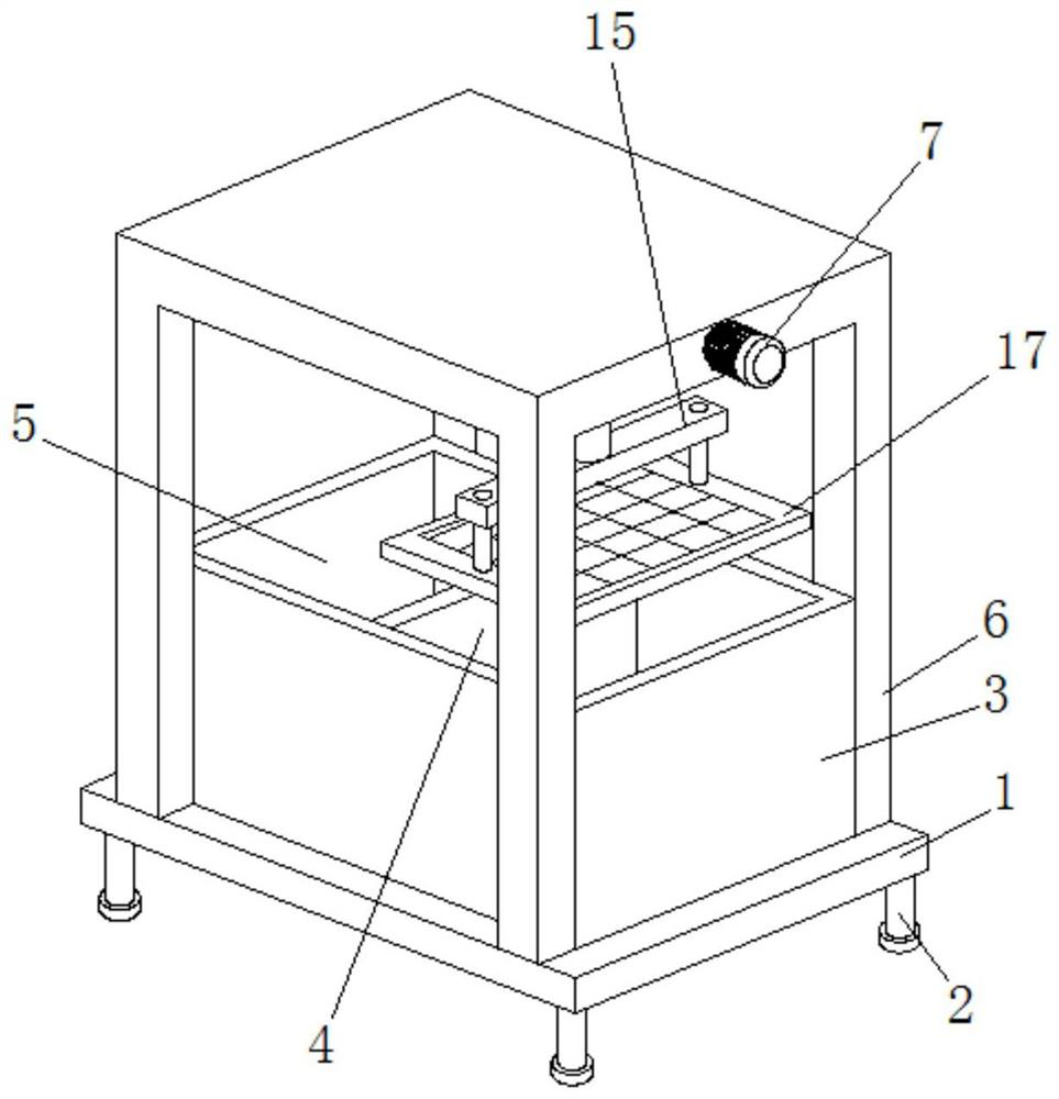
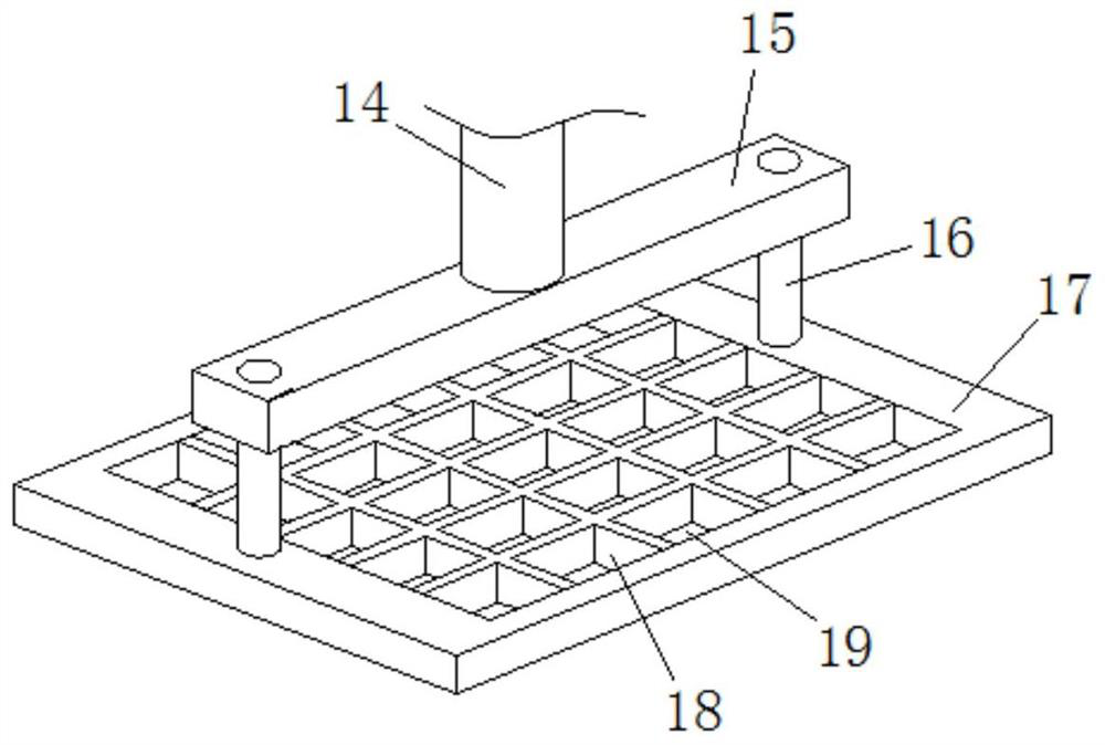
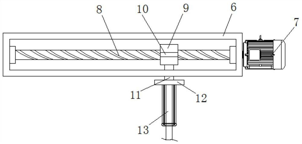
[0021] see Figure 1-4 , the present invention provides a technical solution: an energy-saving ultrasonic cleaning machine for corrosion-resistant ceramic shaft sleeve processing, including a base 1, a support foot 2 is fixedly installed on the lower end of the base 1, and an ultrasonic cleaning body 3 is fixedly installed on the upper end of the base 1 The front end of the ultrasonic cleaning body 3 is fixedly equipped with a cleaning tank 4, the rear end of ...


PUM


Abstract

The invention discloses an ultrasonic cleaning machine for machining an energy-saving corrosion-resistant ceramic shaft sleeve. The ultrasonic cleaning machine comprises a base, supporting legs are fixedly installed at the lower end of the base, an ultrasonic cleaning machine body is fixedly installed at the upper end of the base, a cleaning tank is fixedly arranged at the front end of the interior of the ultrasonic cleaning machine body, an air drying groove is fixedly formed in the rear end of the interior of the ultrasonic cleaning machine body, a supporting frame is fixedly installed at the position, located on the outer side of the ultrasonic cleaning machine body, of the upper end of the base, a rotating motor is fixedly installed at the front end of the upper end of the supporting frame, and the transmission end of the rotating motor extends into the supporting frame. According to the ultrasonic cleaning machine for machining the energy-saving corrosion-resistant ceramic shaft sleeve, cleaning liquid on the surface of the ceramic shaft sleeve is air-dried, the situation that the cleaning liquid remains on the surface of the ceramic shaft sleeve to affect subsequent production operation can be avoided, the production efficiency is effectively improved, meanwhile, subsequent machining of the ceramic shaft sleeve is more convenient, and convenience is further improved.

Description

technical field [0001] The invention relates to the technical field of ultrasonic cleaning machines, in particular to an energy-saving ultrasonic cleaning machine for processing corrosion-resistant ceramic bushings. Background technique [0002] Ultrasonic Cleaner (Ultrasonic Cleaner) uses the high-frequency oscillation signal sent by the ultrasonic generator to cause the liquid to undergo a "cavitation effect" and generate a powerful shock wave, thereby peeling off the dirt layer. The advantages of the ultrasonic cleaner are good cleaning effect and simple operation , Widely used in surface spraying treatment industry, machinery industry, electronics industry, etc. [0003] When processing and cleaning the corrosion-resistant ceramic bushing, due to the special structure of the ceramic bushing, it is easy to squeeze and stack when cleaning the inside of the cleaning box, resulting in damage to the ceramic bushing and lifting the surface of the ceramic bushing after cleaning...

Claims


Application Information

Patent Timeline
IPC IPC(8): B08B3/12B08B13/00F26B21/00
CPCB08B3/12B08B13/00F26B21/004
Inventor 张玉峰李冠芝
Owner 上海晶石陶瓷有限公司
Features
  • Generate Ideas
  • Intellectual Property
  • Life Sciences
  • Materials
  • Tech Scout
  • Unparalleled Data Quality
  • Higher Quality Content
  • 60% Fewer Hallucinations
Learn More