Indexable non-standard double-edge cutting and grooving blade for numerical control

A blade and non-standard technology, which is applied in the direction of lathe tools, accessories of toolholders, turning equipment, etc., can solve the problems of long manufacturing cycle, difficult frictional heat, increased cutting force, etc., and achieve good positioning accuracy and installation firm effect

Pending Publication Date: 2021-06-01
SUZHOU AHNO PRECISION CUTTING TECH CO LTD
View PDF0 Cites 0 Cited by
  • Summary
  • Abstract
  • Description
  • Claims
  • Application Information

AI Technical Summary

Problems solved by technology

The existing CNC indexable tools have the following defects in cutting and grooving: 1. The cutting head of the grooving knife is long and narrow, with poor rigidity and easy to vibrate; 2. The cutting deformation is large. During cutting, the grooving knife consists of a The main cutting edge, two auxiliary cutting edges and two tool nose arcs work at the same time, and the chips are rubbed and squeezed by both sides when they are discharged; 3. The cutting force is large. For round turning, the cutting force increases by 20%-25%; 4. The cutting heat is relatively concentrated, and the cutting edge works in a semi-closed state during grooving
Surrounded by workpieces and chips, and the heat dissipation area of ​​the grooving knife is small, the deformation heat and friction heat are not easily transmitted, resulting in high cutting temperature, which is concentrated at the cutting edge, thus exacerbating tool wear; 5. Chip removal is difficult, When chips are discharged in a narrow slot, they are affected by the large frictional resistance on both sides of the slot, and the broken chips may be stuck in the slot and cause vibration, which makes chip removal difficult and damages the tool; 6. The market CNC is very Standard grooving inserts are expensive and have a long manufacturing cycle

Method used


Image

  • Indexable non-standard double-edge cutting and grooving blade for numerical control
  • Indexable non-standard double-edge cutting and grooving blade for numerical control
  • Indexable non-standard double-edge cutting and grooving blade for numerical control

Examples


Embodiment Construction

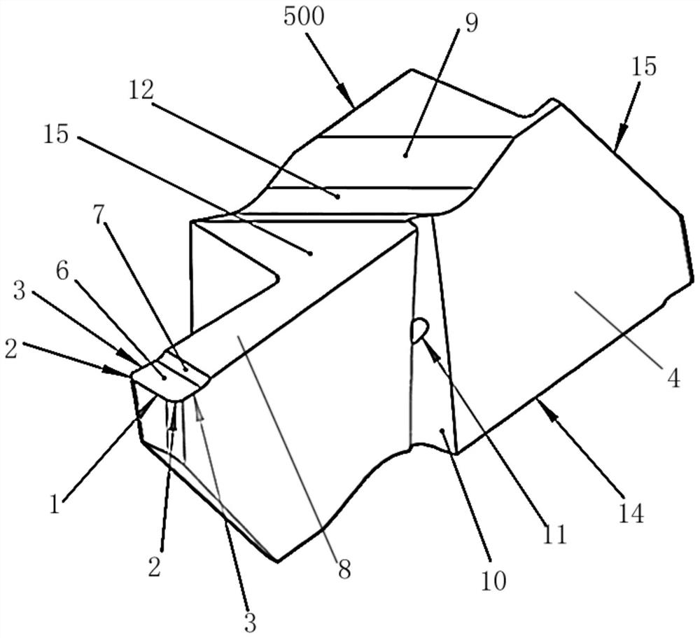
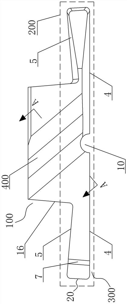
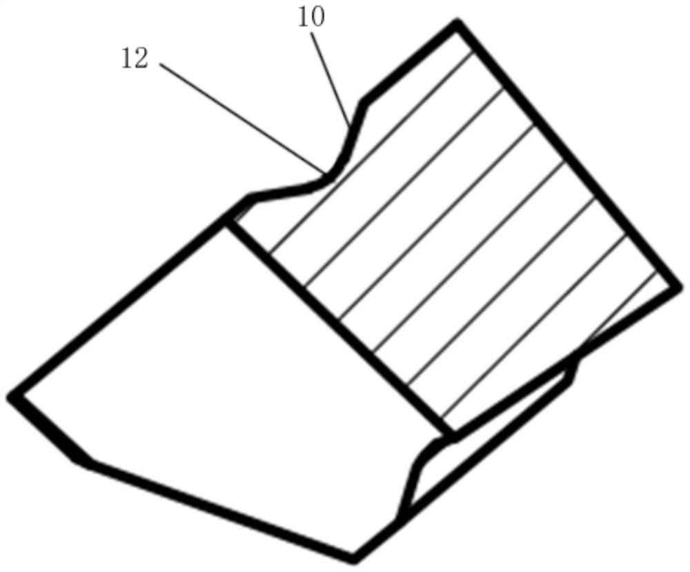
[0017] A non-standard double-edged parting and grooving blade for CNC indexable, see Figure 1-Figure 4 : It comprises a blade body 100, wherein a pair of diagonal positions of the cutting end 200 at the axially outer end of the blade body 100 are respectively provided with cutting unit parts 300, and any one cutting unit part 300 rotates 180° under the cutting state of the blade body 100 coincide with another stationary cutting unit part 300, each cutting unit part 300 includes a cutting edge, a chip breaker, and a chip guiding part. The cutting edge includes a main cutting edge 1 and an arc cutting edge 2. The main cutting edge The two sides of 1 are connected to the starting end of the arc cutting edge 2 on the corresponding side, the outer end of the arc cutting edge 2 is respectively connected to the corresponding minor cutting edge 3, and the outer end surface 4 and the inner side of the two minor cutting edges 3 correspond to The end surface 5 is concavely arranged from...


PUM


Abstract

According to the indexable non-standard double-edge cutting-off and grooving blade for numerical control, the chip breaking and discharging performance is good through the improved chip breaking groove type, and the precise locking and attaching structure enables installation to be firm, shock-resistant, abrasion-resistant and good in shape and position precision. Cutting unit parts are arranged at the positions of a pair of opposite angles of the cutting end of the axial outer end of a blade body correspondingly, any one cutting unit part coincides with the other stationary cutting unit part when the blade body rotates by 180 degrees in the cutting state, each cutting unit part comprises a cutting edge, a chip breaker groove and a chip guide part, the cutting edge comprises a main cutting edge body and arc cutting edge bodies, the two sides of the main cutting edge body are connected with the starting ends of the arc cutting edge bodies on the corresponding sides, the outer side ends of the arc cutting edge bodies are connected with the corresponding auxiliary cutting edge bodies correspondingly, and the outer side end face and the inner side end face corresponding to the two auxiliary cutting edges are concavely arranged from the position of the tool nose to the position away from the tool nose.

Description

technical field [0001] The invention relates to the technical field of cutting tool structures, in particular to a non-standard double-edged cutting and grooving insert used for numerical control indexing. Background technique [0002] As an advanced tool, the indexable tool has the advantages of high hardness, high durability, quick replacement, long tool life, and low tool cost, and is widely used in cutting processing. The existing CNC indexable tools have the following defects in cutting and grooving: 1. The cutting head of the grooving knife is long and narrow, with poor rigidity and easy to vibrate; 2. The cutting deformation is large. During cutting, the grooving knife consists of a The main cutting edge, two auxiliary cutting edges and two tool nose arcs work at the same time, and the chips are rubbed and squeezed by both sides when they are discharged; 3. The cutting force is large. For circular turning, the cutting force increases by 20%-25%; 4. The cutting heat i...

Claims


Application Information

Patent Timeline
IPC IPC(8): B23B27/06B23B27/16
CPCB23B27/06B23B27/1648
Inventor 甘其龙沈钰殷亚军欧望达
Owner SUZHOU AHNO PRECISION CUTTING TECH CO LTD
Why Eureka
Try Eureka