Spot welding device for computer spare and accessory part machining

A technology of spot welding device and spare parts, applied in metal processing equipment, manufacturing tools, welding equipment and other directions, can solve the problems of computer spare parts extrusion that is not easy to control, computer spare parts cannot be used normally, and computer spare parts are damaged, etc. Achieve the effect of avoiding spot welding position offset, realizing rational utilization, and ensuring normal use

Inactive Publication Date: 2021-06-01
阳江尚跃凯智能科技有限公司
View PDF0 Cites 0 Cited by
  • Summary
  • Abstract
  • Description
  • Claims
  • Application Information

AI Technical Summary

Problems solved by technology

[0002] A computer is an electronic device that can automatically process and process various data and information according to instructions. It is composed of multiple spare parts. The processing of computer spare parts is more cumbersome and fine. In terms of computer parts, it is necessary to perform spot welding on the exact position of computer parts. During the use of existing spot welding devices for computer parts processing, computer parts will be crushed and the position of spot welding will be shifted.
[0003] During the working process of the existing spot welding device for computer spare parts processing, it is difficult to control the extrusion of computer parts by the spot welding device. When the extrusion force is too large, it will cause damage to computer parts and computer parts. Accessories cannot be used normally, resulting in a waste of resources. When the pressure is insufficient, the spot welding position of computer parts will shift during the processing process, resulting in damage to computer parts and economic losses.

Method used


Image

  • Spot welding device for computer spare and accessory part machining
  • Spot welding device for computer spare and accessory part machining
  • Spot welding device for computer spare and accessory part machining

Examples


Embodiment Construction

[0024] The following will clearly and completely describe the technical solutions in the embodiments of the present invention with reference to the accompanying drawings in the embodiments of the present invention. Obviously, the described embodiments are only some, not all, embodiments of the present invention. Based on the embodiments of the present invention, all other embodiments obtained by persons of ordinary skill in the art without making creative efforts belong to the protection scope of the present invention.

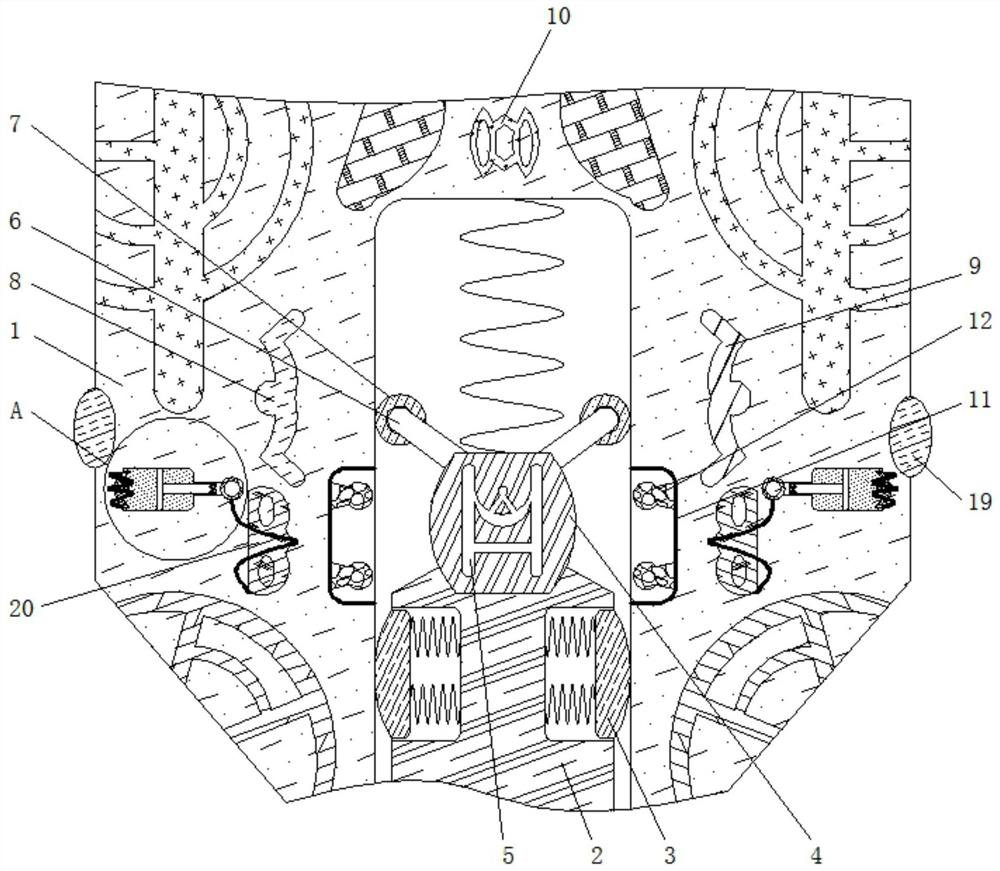
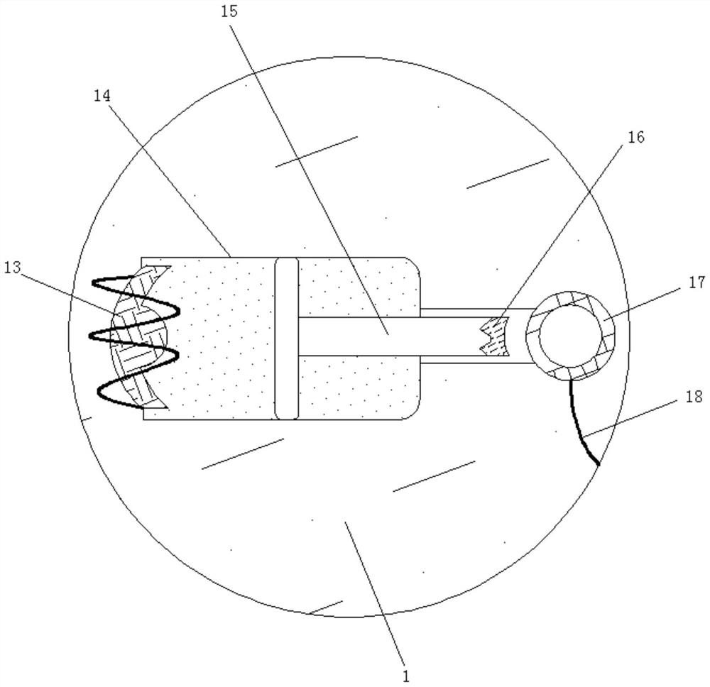
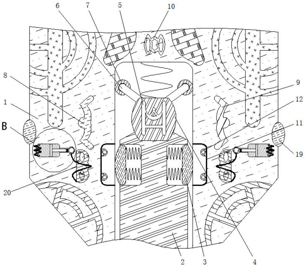
[0025] see Figure 1-4 , a spot welding device for processing computer spare parts, including a housing 1, the inner wall of the housing 1 is elastically connected with a slider 4, the material of the slider 4 is stainless steel, and the structure of the roller shaft 7 is a ring structure , the roller shaft 7 is symmetrically distributed on both sides of the slider 4, the slider 4 plays a sliding role, the top of the slider 4 is fixedly connected to the connec...


PUM


Abstract

The invention relates to the technical field of computer spare and accessory parts, and discloses a spot welding device for computer spare and accessory part machining. The spot welding device for computer spare and accessory part machining comprises a shell, wherein a sliding block is elastically connected to the inner wall of the shell; a connecting rod is fixedly connected to the top of the sliding block; a roller shaft is movably connected to the outer side of the connecting rod; a dielectric plate is fixedly connected to the inner wall of the sliding block; the bottom of the sliding block is fixedly connected with a welding head; and the inner wall of the welding head is elastically connected with a limiting block. According to the spot welding device for computer spare and accessory part machining, through shrinkage of a magnetostrictive shrinkage rod, extrusion of the spot welding device on the computer spare and accessory parts is conveniently controlled, and the extrusion force is prevented from being too large, so that damage to the computer spare and accessory parts is avoided, normal use of the computer spare and accessory parts is guaranteed, and resources are saved; and insufficient pressure is avoided, so that in the machining process of the computer spare and accessory parts, the phenomenon of spot welding position deviation is avoided, the computer spare and accessory parts are prevented from being damaged, and economic losses are avoided.

Description

technical field [0001] The invention relates to the technical field of computer spare parts, in particular to a spot welding device for processing computer spare parts. Background technique [0002] A computer is an electronic device that can automatically process and process various data and information according to instructions. It is composed of multiple spare parts. The processing of computer spare parts is more cumbersome and fine. In terms of computer parts, it is necessary to carry out spot welding on the exact position of the computer parts. During the use of the existing spot welding device for computer parts processing, the computer parts will be crushed and the position of the spot welding will be shifted. [0003] During the working process of the existing spot welding device for computer spare parts processing, it is difficult to control the extrusion of computer parts by the spot welding device. When the extrusion force is too large, it will cause damage to com...

Claims


Application Information

Patent Timeline
Patent Type & Authority Applications(China)
IPC IPC(8): B23K11/11B23K31/02
CPCB23K11/11B23K31/02
Inventor 李璐
Owner 阳江尚跃凯智能科技有限公司
Why Eureka
Try Eureka