A concrete prefabricated block production equipment

A technology for production equipment and prefabricated blocks, applied in clay preparation devices, chemical instruments and methods, cement mixing devices, etc., can solve problems such as the influence of concrete molding, the easy adhesion of concrete to mixing blades, etc., and achieve the effect of avoiding solidification

Active Publication Date: 2022-08-09
四川开全新型材料科技有限公司
View PDF9 Cites 0 Cited by
  • Summary
  • Abstract
  • Description
  • Claims
  • Application Information

AI Technical Summary

Problems solved by technology

[0003] However, when the mixing equipment is working, the concrete is stirred through the outer end of the mixing blade. When the mixing blade rotates slowly, the concrete driven to the top by the rotation of the mixing blade falls because of insufficient speed, and hits the mixing blade of the next stage. Above all, the concrete on the surface layer will naturally flow back into the concrete material, and the concrete that hits the mixing blade first will easily stick to the mixing blade, which will affect the weight of the mixing blade and cause the stirring blade to shake when it rotates, which will affect the shaping of the concrete. influences

Method used


Image

  • A concrete prefabricated block production equipment
  • A concrete prefabricated block production equipment
  • A concrete prefabricated block production equipment

Examples


Embodiment 1

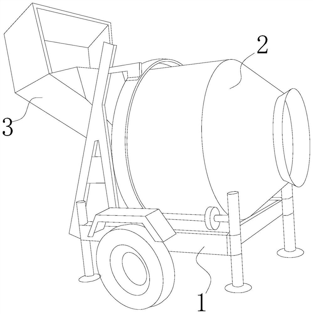
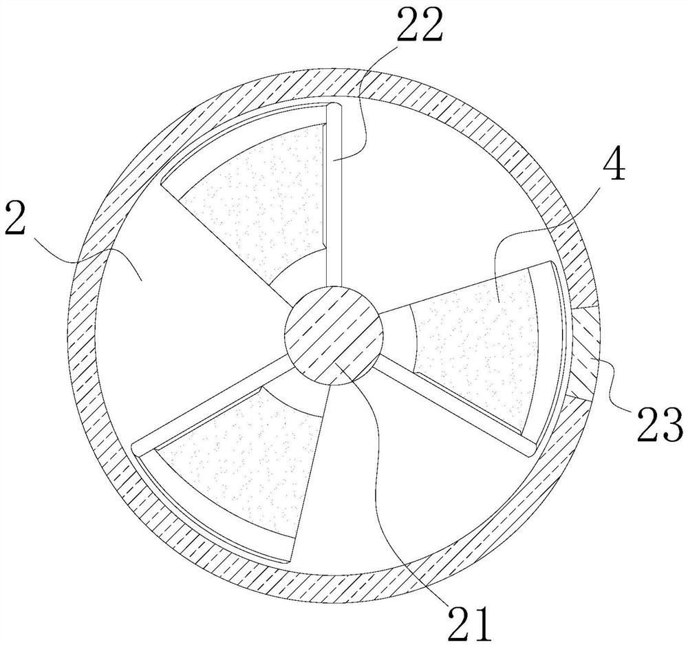
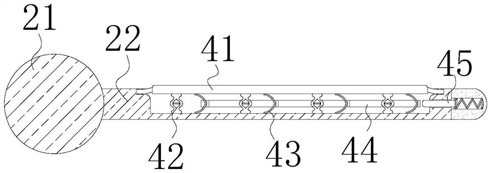
[0026] like Figure 1-Figure 3 As shown, the present invention provides a concrete precast block production equipment, the structure of which includes: a frame 1, a mixing bucket 2, a hopper 3, and a swinging device 4, the mixing bucket 2 is installed on the frame 1, and the hopper 3 It is arranged at the rear of the stirring barrel 2, and the stirring barrel 2 is provided with a stirring shaft 21, a stirring blade 22, and a magnet bar 23. The stirring shaft 21 is arranged in the stirring barrel 2 along the axis of the stirring barrel 2. The stirring blade 22 is in the shape of a curved plate and is arranged on the stirring shaft 21, the magnet bar 23 is arranged on the right side of the stirring bucket 2 and the inclination is matched with the curvature of the stirring blade 22, and the swinging device 4 is arranged on the stirring blade 22. On the top surface of the upper surface, the swinging device 4 is composed of a pressure plate 41, an upper spring column 42, a lower bi...

Embodiment 2

[0033] like Figure 1-Figure 3 As shown, the present invention provides a concrete precast block production equipment, the structure of which includes: a frame 1, a mixing bucket 2, a hopper 3, and a swinging device 4, the mixing bucket 2 is installed on the frame 1, and the hopper 3 It is arranged at the rear of the stirring barrel 2, and the stirring barrel 2 is provided with a stirring shaft 21, a stirring blade 22, and a magnet bar 23. The stirring shaft 21 is arranged in the stirring barrel 2 along the axis of the stirring barrel 2. The stirring blade 22 is in the shape of a curved plate and is arranged on the stirring shaft 21, the magnet bar 23 is arranged on the right side of the stirring bucket 2 and the inclination is matched with the curvature of the stirring blade 22, and the swinging device 4 is arranged on the stirring blade 22. On the top surface of the upper surface, the swinging device 4 is composed of a pressure plate 41, an upper spring column 42, a lower bi...


PUM


Abstract

The invention discloses a concrete prefabricated block production equipment. Its structure comprises: a frame, a mixing bucket, a hopper, and a swinging device. The mixing bucket is provided with a mixing shaft, a mixing blade and a magnet strip, and the swinging device is arranged on the side of the mixing blade. On the top surface, the swinging device is composed of a pressure plate, an upper spring column, a lower clip, a push frame, and a shock mechanism. The upper spring column and the lower clip together abut against the bottom end of the pressure plate and the inside of the stirring blade. , the push frame is fixedly connected to the arched end of the lower bite clip, and the shock mechanism is arranged at the outer end of the mixing blade. In the present invention, a swinging device is provided on the upper end surface of the mixing blade, so that the concrete stirred to the high place is smashed to the ground. When the mixing blade goes up, it hits the pressure plate in advance, and the lower clip drives the pressure plate to further press down, and together with the upper spring column drives the pressure plate to bounce, so that the pressure plate will shake up and down when it is hit by concrete. Shake off the concrete as soon as possible to prevent the concrete from solidifying on the mixing blade and affect the concrete mixing effect.

Description

technical field [0001] The invention relates to the field of concrete equipment, in particular to a production equipment for concrete prefabricated blocks. Background technique [0002] During the production of concrete prefabricated blocks, the concrete is mixed and produced by a mixer, and then put into the prefabricated block abrasive tool for molding; [0003] However, when the mixing equipment is working, the concrete is mixed through the outer end of the mixing blade. When the mixing blade rotates slowly, the concrete at the top driven by the rotation of the mixing blade falls down because of insufficient speed and hits the mixing blade at the next level. On the other hand, the concrete on the surface layer will naturally flow back into the concrete, and the concrete that hits the mixing blade first is easy to stick to the mixing blade, which affects the weight of the mixing blade and causes the mixing blade to shake when it rotates, which will cause damage to the mold...

Claims


Application Information

Patent Timeline
Patent Type & Authority Patents(China)
IPC IPC(8): B28C5/14B28C5/08
CPCB28C5/14B28C5/0806
Inventor 江以航
Owner 四川开全新型材料科技有限公司
Why Eureka
Try Eureka