Injection mold

A technology of injection mold and mold bottom plate, which is applied in the direction of coating, etc., can solve the problems of reducing the impact force of molten material, increasing the injection cycle, floating, etc., and achieve the effect of improving production pass rate and increasing stability

Active Publication Date: 2021-06-01
NINGBO FUERDA SMARTECH CO LTD
View PDF7 Cites 0 Cited by
  • Summary
  • Abstract
  • Description
  • Claims
  • Application Information

AI Technical Summary

Problems solved by technology

If the finished plastic insert contains a large plate insert that is mainly used to enhance the strength of the plastic part, and there are relatively few small inserts that are fixed and exposed to the large plate insert, it is equivalent to the large plate insert There are few supporting points, so when the large-scale plate inserts are suspended in the air and do not reach the supporting points during injection molding, they are easy to float, shift or even be exposed under the impact of the melting material. The final result is that defective products that are prone to insert displacement Production pass rate is not high
Although it is possible to reduce the impact force of the melted material by reducing the feed amount of the melted material per unit time, this method will significantly increase the injection molding cycle, thereby increasing the cost, which is not advisable

Method used


Image

  • Injection mold
  • Injection mold
  • Injection mold

Examples


Embodiment Construction

[0020]The present invention will be further described below with reference to the accompanying drawings and specific examples.

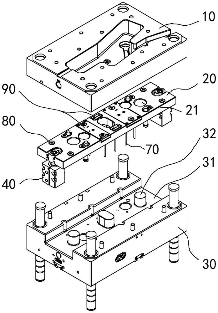
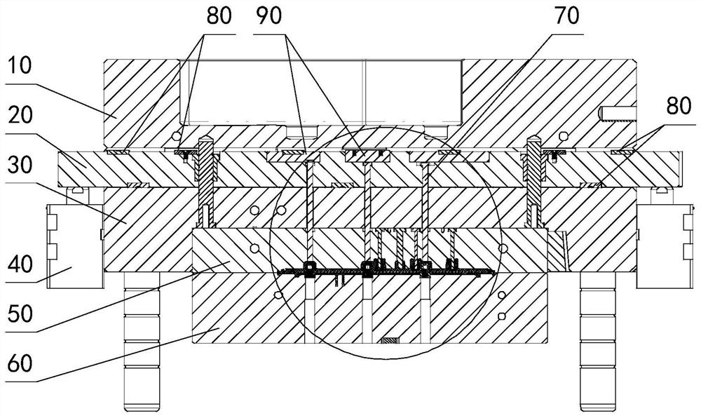
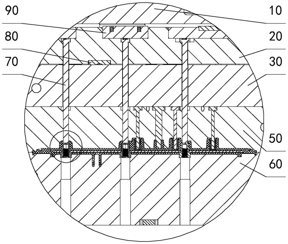
[0021]Example, referring toFigure 1-6 , An injection mold, including upper mold bottom plate 10, upper mold fixing plate 30, upper film 50, lower film 60, hydraulic cylinder 40, limit pin fixing plate 20, limit pin 70, limited pin cover 90 The upper mold fixing plate 30 is fixed to the upper mold bottom plate 10 and the upper film 50, respectively; the top surface of the upper mold fixing plate 30 has a plate groove 31 that penetrates both ends and can place a limit pin fixing plate 20, and the groove 31 The depth is greater than the height of the limit pin fixing plate 20; the limit pin fixing plate 20 is mounted in the groove 31, and the bottom surface of the groove 31 has several positioning columns 32, and the limit pin fixing plate 20 has several positioning posts 32. The hole 21, the rear limit pin fixing plate 20 can only be moved up and down in the gr...


PUM


Abstract

The invention relates to an injection mold. The injection mold comprises an upper mold bottom plate, an upper mold fixing plate, an upper mold core, a lower mold core, a driving cylinder, a limiting needle fixing plate and a limiting needle, wherein the upper mold bottom plate, the upper mold fixing plate, the upper mold core and the lower mold core are fixedly connected; the limiting needle fixing plate is fixed in a plate groove of the upper mold fixing plate, and the depth of the plate groove is larger than the height of the limiting needle fixing plate; one end of the limiting needle is fixedly connected with the limiting needle fixing plate, and the other end of the limiting needle can penetrate through the limiting needle fixing plate, the upper mold fixing plate and the upper mold core to extend into an accommodating cavity formed by the upper mold core and the lower mold core in a matched mode; a piston rod of the driving cylinder moves up and down and can drive the limiting needle fixing plate and the limiting needle to move up and down; and the tail end of the limiting needle moves downwards before injection molding and abuts against a metal piece in the accommodating cavity, and when the injection molding is carried out to a preset degree, the limiting needle moves upwards and is located at the upper edge of a finished product. The injection mold has the beneficial effects that a large plate insert cannot float or move due to the impact force generated when a molten material is injected in the injection molding process, finally, the production stability is improved, and the production percent of pass of products is improved.

Description

Technical field[0001]The present invention relates to the field of injection molding equipment, and more particularly to an injection mold.Background technique[0002]Traditional injection molded products are single plastic parts. With the development of technology and the changes in demand, the insert injection molding process is born, and inserts injection molding is pre-fixed in the injection mold in the injection mold. Then, the molten plastic molding is then injected. After the mold, the insert is cooled, the cured plastic bag is compounded in the plastic to obtain a molding process of integrated product products such as threads, electrodes, etc.[0003]The insert must be well fixed in the mold, otherwise it is easy to displace or deform under the impact of the sol. In actual use, the positioning of the insert is necessary to set the support in the upper film or the lower film. However, it is foreseeable that the insert is ultimately formed with plastic, and finally takes out with ...

Claims


Application Information

Patent Timeline
IPC IPC(8): B29C45/14B29C45/26
CPCB29C45/14065B29C45/26
Inventor 余周波陈科丁佳元
Owner NINGBO FUERDA SMARTECH CO LTD
Why Eureka
Try Eureka