
Cable reel

A cable reel and reel technology, which is applied in the field of cable reels, can solve the problems of hysteresis couplings being easily burned out, poor cable following effect, and small number of permanent magnets, etc., to improve power factor and overcome difficult adjustments , good follow-up effect

Inactive Publication Date: 2021-06-01
苏希俭
View PDF0 Cites 0 Cited by
  • Summary
  • Abstract
  • Description
  • Claims
  • Application Information

AI Technical Summary

Problems solved by technology

With the accumulation of heat, if things go on like this, the hysteresis coupling is easy to be burned out
Thirdly, the number of permanent magnets on the permanent disk is small, the magnetic induction torque is small, and the cable following effect is poor when the reel is switched from high-speed forward to reverse
Secondly, the prior art is self-heavy and has large dimensions
Finally, the existing technology has a low efficiency of converting electrical energy into mechanical energy

Method used


Image

  • Cable reel
  • Cable reel
  • Cable reel

Examples


Embodiment Construction

[0044] The same reference numerals will be used throughout the drawings to refer to the same or like parts. Although the terms used are selected from well-known and commonly used terms, some terms require related descriptions in this specification to understand the detailed meanings in the present invention.

[0045] In order to avoid obscuring or obscuring the focus of the present invention, some specific details have been omitted from the description.

[0046] In order to better understand the improvement made by the present invention compared with the prior art, before describing the specific implementation of the present invention in detail, the prior art mentioned in the background art section will be described with reference to the accompanying drawings.

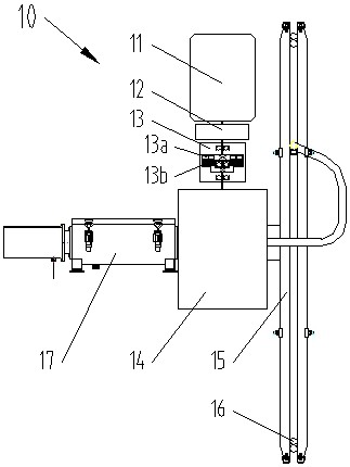
[0047] Prior art cable reel (10), see figure 1, its composition and transmission principle are: motor (11) → brake (12) → hysteresis coupling (13) → reduction box (14) → reel (15) → cable (16) → slip ring box (17 ). ...


PUM


Abstract

The invention discloses a cable reel. The cable reel is characterized in that a plurality of rare earth permanent magnets are fixed on the inner circle surface of a retainer to form an outer rotor of a motor; an iron core and a winding are fixed on a hollow shaft to form a stator of the motor; the outer rotor and the stator are connected through a high-strength bolt pair, a small end cover, a large end cover and a rolling bearing to form the motor; a reel seat and the retainer form a sliding bearing; the reel seat, an adjusting gasket, an adjusting bolt and an induction ring form an assembly, the retainer and the rare earth permanent magnets form an assembly, and the two assemblies form a hysteresis coupling; a reel and the reel seat rotate around the hollow shaft together through the hysteresis coupling to form the cable reel. The assembly formed by the retainer and the rare earth permanent magnets has three functions, namely the outer rotor of the motor, an inner ring of the sliding bearing and a permanent magnet ring of the hysteresis coupling; The assembly formed by the reel seat, the adjusting gasket, the adjusting bolt and the induction ring has two functions, namely the outer ring of the sliding bearing and the induction ring of the hysteresis coupling.

Description

technical field [0001] The invention relates to a cable reel, which is used for winding cables. This cable can be used for the transmission of electric power, control signals, communication signals, etc. of the whole crane or crane spreader. Background technique [0002] Rail cranes used in the open air, transmission cables for power, control signals, and communication signals of the whole machine or spreader, often use cable reels to wind the cables to retract and unwind the cables. Since the number of winding turns of the cable on the reel is increasing and decreasing all the time, and the diameter of the cable winding is changing all the time, the phenomenon that the motor of the cable reel runs at the same speed but the speed of the cable is different. The operating speed of the crane or the lifting speed of the spreader is constantly changing due to the needs of the work. The speed of cable retracting and unwinding often does not match the speed of the crane or the sp...

Claims


Application Information

Patent Timeline
Patent Type & Authority Applications(China)
IPC IPC(8): B65H75/44
CPCB65H75/44B65H75/4442B65H75/4486B65H2701/34
Inventor 苏希俭
Owner 苏希俭
Learn More