Bricklaying machine for automatic construction engineering

A technology of construction engineering and bricklaying machine, which is applied in the direction of construction, building structure, and construction material processing, etc., and can solve problems such as difficult guarantee of worker safety, poor working environment conditions, and high labor intensity of workers

Active Publication Date: 2022-03-29
嘉兴瑞达建设有限公司
View PDF7 Cites 0 Cited by
  • Summary
  • Abstract
  • Description
  • Claims
  • Application Information

AI Technical Summary

Problems solved by technology

[0002] At present, most of the bricklaying methods on the market are artificial bricklaying methods, and usually in the process of laying bricks, there are many processes, such as bricklaying transfer, bricklaying plastering, and bricklaying. These processes are performed by the same When a worker or a few workers complete the work, the labor intensity of the workers is high, the efficiency is low, the working environment conditions are poor, the work cost is high, and the safety of the workers is not easy to guarantee
[0003] With the continuous development of the construction industry and the continuous advancement of science and technology, traditional operating methods can no longer adapt to the requirements of the times, and cannot meet the needs of safe, efficient and automated construction processes

Method used


Image

  • Bricklaying machine for automatic construction engineering
  • Bricklaying machine for automatic construction engineering
  • Bricklaying machine for automatic construction engineering

Examples


Embodiment Construction

[0031] The specific implementation manners of the present invention will be further described in detail below in conjunction with the accompanying drawings and embodiments. The following examples are used to illustrate the present invention, but are not intended to limit the scope of the present invention.

[0032] The following reference Figure 1 to Figure 5 The present invention will be described.

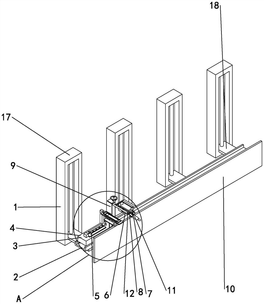
[0033] A bricklaying machine for automatic construction engineering, comprising a lifting mechanism 1, a track 2 is laid on the lifting mechanism 1, and a bricklaying vehicle 3 is arranged on the track 2. The brick-laying vehicle 3 moves on the track 2. After the brick-laying vehicle 3 finishes laying a brick, the brick-laying vehicle 3 moves a distance of one brick length in the horizontal direction to continue laying bricks; the lifting mechanism 1 can Bricklaying vehicle 3 lifts, and after bricklaying vehicle 3 sticks one layer of bricks, lifting mechanism 1 lifts bricklayi...


PUM


Abstract

The invention discloses a brick-laying machine for automatic construction engineering, which comprises a lifting mechanism, a track is laid on the lifting mechanism, a brick-laying vehicle is arranged on the track, an installation platform is installed on the brick-laying vehicle, and a brick-feeding mechanism is installed on the installation platform , a bricklaying mechanism and a cementing mechanism, the bricklaying mechanism includes a fixed frame, and a bricklaying frame is provided on the installation platform, and the fixed frame is fixedly installed on the bricklaying frame. It is a brick wall, and the fixed frame is installed obliquely. The two sides of the fixed frame are sliding sleeves. The internal cross section of the sliding sleeve is square. There are two sliding sleeves, and one end of the sliding sleeve is provided with a bricklaying cylinder. One, the sliding sleeves are equipped with sliders, the sliders are connected to the piston rod of the bricklaying cylinder one, the sides of the sliders are connected to the pneumatic telescopic rods, and the sliding sleeves are provided with The strip-shaped opening for the movement of the pneumatic telescopic rod, and the end of the pneumatic telescopic rod far away from the slider is provided with a brick clamping assembly.

Description

technical field [0001] The invention relates to the technical field of wall-laying brick machines, in particular to a brick-laying machine for automatic construction engineering. Background technique [0002] At present, most of the bricklaying methods on the market are artificial bricklaying methods, and usually in the process of laying bricks, there are many processes, such as bricklaying transfer, bricklaying plastering, and bricklaying. These processes are performed by the same When a worker or a few workers finish, the worker's labor intensity is high, the efficiency is low, the operating environment condition is poor, the operating cost is high, and the worker's safety is not easy to guarantee. [0003] With the continuous development of the construction industry and the continuous advancement of science and technology, traditional operating methods can no longer adapt to the requirements of the times, and cannot meet the needs of safe, efficient and automated construc...

Claims


Application Information

Patent Timeline
Patent Type & Authority Patents(China)
IPC IPC(8): E04G21/22E04G21/20
CPCE04G21/22E04G21/206
Inventor 徐晓波陆建丰刘松烽
Owner 嘉兴瑞达建设有限公司
Why Eureka
Try Eureka