
Electronic expansion valve

A technology of electronic expansion valve and valve needle, which is applied in the direction of lifting valve, valve device, lighting and heating equipment, etc., can solve the problems of wear and affect the life of electronic expansion valve, and achieve the effect of reducing wear

Pending Publication Date: 2021-06-01
ZHEJIANG SANHUA INTELLIGENT CONTROLS CO LTD
View PDF0 Cites 1 Cited by
  • Summary
  • Abstract
  • Description
  • Claims
  • Application Information

AI Technical Summary

Problems solved by technology

[0003] When the valve needle is in contact with the valve port, the downward force on the valve needle will affect the life of the electronic expansion valve. If the valve needle receives a large downward force when it is in contact with the valve port, the valve needle will easily move relative to the valve port. Rotation, it is easy to cause wear of both due to the relative rotation of the valve needle and valve port

Method used


Image

  • Electronic expansion valve
  • Electronic expansion valve
  • Electronic expansion valve

Examples


Embodiment Construction

[0021] In order to enable those skilled in the art to better understand the technical solutions of the present invention, the present invention will be further described in detail below in conjunction with the accompanying drawings and specific embodiments.

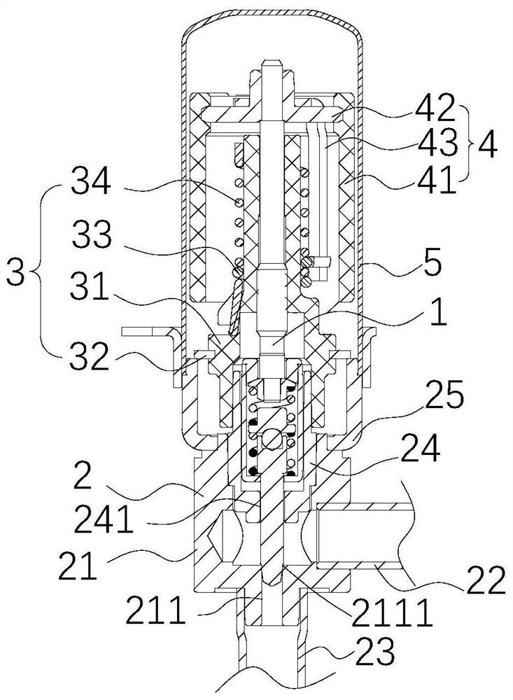
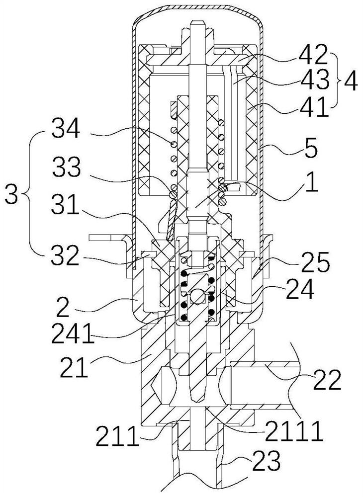
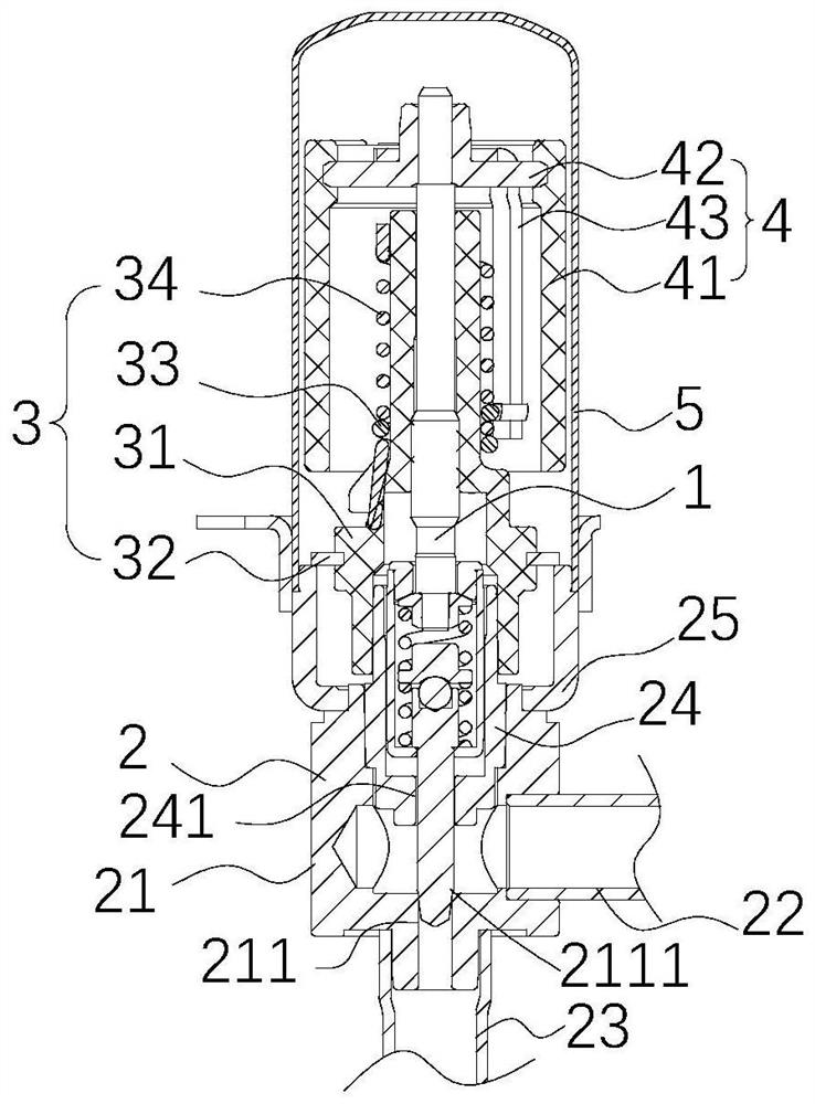
[0022] Please refer to Figure 1 to Figure 7 ,in, figure 1 It is a sectional view of the fully closed state of the first embodiment of the electronic expansion valve provided by the present invention, figure 2 Partial cross-sectional view of the first embodiment of the electronic expansion valve provided by the present invention when fully open, image 3 for image 3 A partial cross-sectional view of the first embodiment of the electronic expansion valve provided by the present invention when the needle is just in contact with the sealing part of the valve port, Figure 4 for figure 2 Cutaway view of the middle valve pin screw assembly, Figure 5 for Figure 4 Exploded view of the middle valve pin screw assembly, ...


PUM


Abstract

The invention relates to an electronic expansion valve which comprises a valve needle screw rod assembly. The valve needle screw rod assembly comprises a valve needle, a sleeve component, an upper spring, a lower spring, an elastic carrier component and a screw rod component; the screw rod component comprises a screw rod body part and an abutting part; the screw rod body part and the abutting part are fixedly connected or are of an integrated structured; the screw rod component is connected with the sleeve component in a limiting mode; the valve needle comprises a large-diameter section and a small-diameter section; the valve needle is connected with the sleeve component in a limiting mode; the upper spring, the lower spring and the elastic carrier component are located in the sleeve component; the upper end of the upper spring abuts against the abutting part; the lower end of the upper spring abuts against the elastic carrier component; the upper end of the lower spring abuts against the elastic carrier component; and the lower end of the lower spring abuts against the sleeve component. The abrasion of the valve needle and a valve port caused by relative rotation can be reduced conveniently by changing the elastic force of the upper spring and the lower spring to the elastic carrier component in the initial state.

Description

【Technical field】 [0001] The invention relates to the technical field of refrigeration control, in particular to an electronic expansion valve. 【Background technique】 [0002] The electronic expansion valve is mainly used in the refrigeration system. The rotation of the rotor is controlled by the electromagnetic coil. Through the cooperation of the screw and the nut, the valve needle is close to or far away from the valve port, thereby adjusting the flow area of ​​the valve port to realize the flow rate of the refrigerant. adjust. [0003] When the valve needle is in contact with the valve port, the downward force on the valve needle will affect the life of the electronic expansion valve. If the valve needle receives a large downward force when it is in contact with the valve port, the valve needle will easily move relative to the valve port. Rotation is easy to cause wear of both due to the relative rotation of the valve needle and the valve port. 【Content of invention】 ...

Claims


Application Information

Patent Timeline
Patent Type & Authority Applications(China)
IPC IPC(8): F16K1/32F16K1/38F16K1/48F25B41/345
CPCF16K1/32F16K1/38F16K1/482
Inventor 不公告发明人
Owner ZHEJIANG SANHUA INTELLIGENT CONTROLS CO LTD
Learn More