High-toughness pipe

A high-toughness, pipe technology, used in rigid pipes, pipes, pipe components, etc., can solve the problems of adjusting the inner wall, hidden dangers, pipe rupture, etc., to improve the buffer capacity, reduce the impact, and improve the service life.

Inactive Publication Date: 2021-06-01
徐如林
View PDF0 Cites 2 Cited by
  • Summary
  • Abstract
  • Description
  • Claims
  • Application Information

AI Technical Summary

Problems solved by technology

[0005] Aiming at the deficiencies of the prior art, the present invention provides a high-toughness pipe, which solves the problem that the existing pipe cannot flexibly adjust the strength and toughness of the inner wall according to the water pressure. The impact causes the pipe to break, and there is a big safety hazard. It enhances the buffering capacity of the pipe, can reduce the impact on the pipe wall when the internal water body flows, and improves the service life of the pipe. Impurities adhere to the inner wall of the pipe

Method used


Image

  • High-toughness pipe
  • High-toughness pipe
  • High-toughness pipe

Examples


Embodiment 1

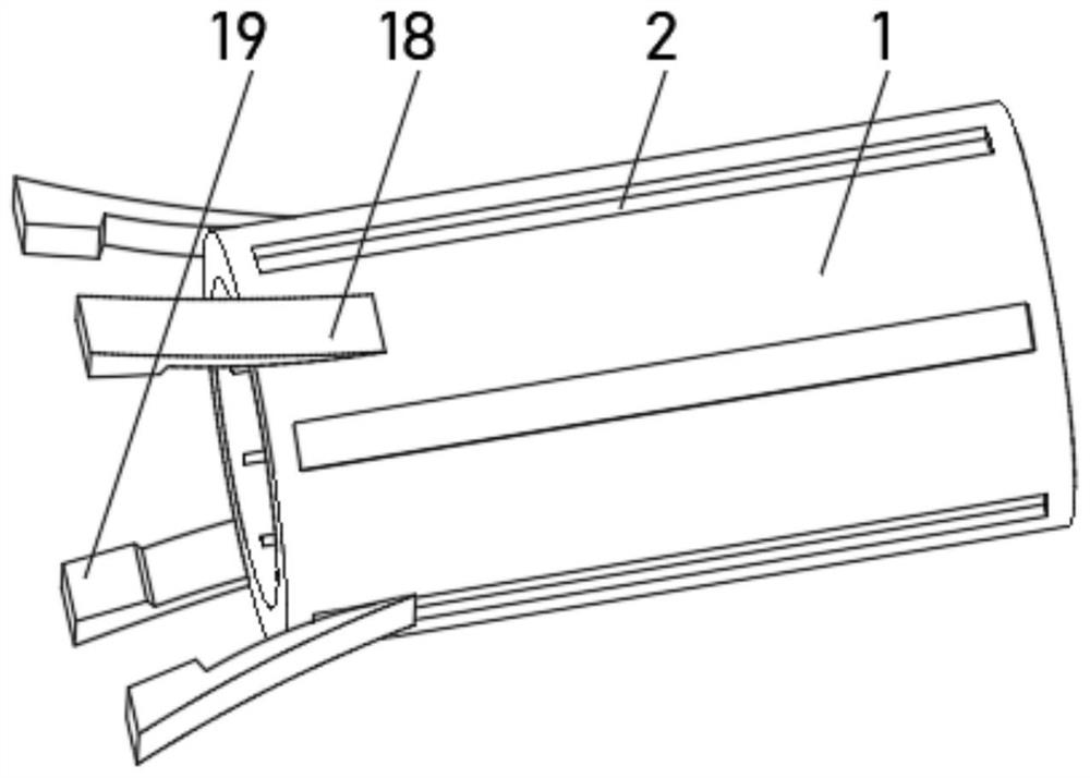
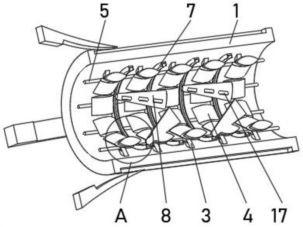
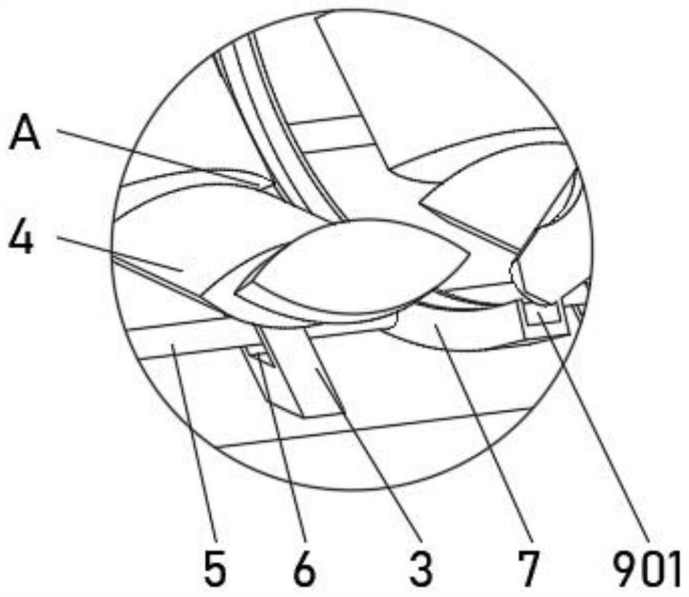
[0029] see Figure 1-4 , the present invention provides a technical solution: a high-toughness pipe, including an outer tube 1, the outer side of the outer tube 1 is evenly provided with an anti-skid groove 2, and the inner wall of the outer tube 1 is evenly equipped with an elastic rod 3, and one end of the elastic rod 3 is fixed Rigid arcs 4 are connected, one side of the elastic rod 3 runs through a pull rope 5, one side of the elastic rod 3 is provided with a guide hole 6 suitable for the pull rope 5, and evenly installed between the pull ropes 5 A control ring 7, a detection rod 8 is evenly installed on one side of the control ring 7, a trigger device 9 is installed inside the control ring 7, and the trigger device 9 is connected with the detection rod 8.

[0030] The trigger device 9 includes a trigger groove 901, one side of the inner wall of the trigger groove 901 is fixedly connected with a constricting block 903 through an elastic rope 902, the pulling rope 5 is fixe...

Embodiment 2

[0037] see Figure 1-4 , the present invention provides a technical solution: on the basis of Embodiment 1, a cleaning device 10 is installed on the inner wall of the outer tube 1 close to the rigid arc 4, the cleaning device 10 includes a swing rod 101, one end of the swing rod 101 is connected to the rigid The arc piece 4 is rotatably connected, and the end of the swing rod 101 away from the rigid arc piece 4 is fixedly connected with a cleaning head 102 , and the cleaning head 102 is slidingly connected with the inner wall of the outer tube 1 .

[0038] A track groove 103 is opened inside the swing rod 101 , and a metal ball 104 is slidably connected to one side of the inner wall of the track groove 103 .

[0039] The inner wall of the outer tube 1 is fixedly connected with the limit block 13 near the position of the swing rod 101, and the limit block 13 is provided with a limit groove 14 on the side close to the swing rod 101, and one side of the inner wall of the limit gr...


PUM


Abstract

The invention discloses a high-toughness pipe. The high-toughness pipe comprises an outer pipe, wherein anti-skid grooves are evenly formed in the outer side of the outer pipe, elastic rods are evenly installed on the inner wall of the outer pipe, one end of the elastic rod is fixedly connected with a rigid arc piece, a traction rope penetrates through one side of the elastic rod, a guide hole matched with a traction rope is formed in one side of the elastic rod, control rings are evenly installed between the traction ropes, detection rods are evenly installed on one side of the control ring, and a trigger device is installed in the control ring and connected with the detection rods. The invention relates to the technical field of pipes. According to the high-toughness pipe, the purpose of flexibly adjusting the strength and toughness of the inner wall according to water pressure is achieved, the buffering capacity of the pipe is enhanced, impact on the pipe wall when internal water flows can be weakened, the service life of the pipe is prolonged, the high-toughness pipe has the cleaning capacity, and impurities can be prevented from being attached to the inner wall of the pipe after long-time use.

Description

technical field [0001] The invention relates to the technical field of pipes, in particular to a high-toughness pipe. Background technique [0002] The pipe is a device used to transport gas, liquid or fluid with solid particles. Usually, after the fluid is pressurized by blowers, compressors, pumps and boilers, it flows from the high pressure of the pipe to the low pressure. The pressure of the fluid itself can also be used Or gravity transportation, pipes are widely used, mainly used in water supply, drainage, heat supply, gas supply, long-distance transportation of oil and natural gas, agricultural irrigation, hydraulic engineering and various industrial installations. [0003] Pipes are often used in water conservancy transportation, but the existing water utilization pipes cannot flexibly adjust the strength and toughness of the inner wall according to the water pressure. Big safety hazard, lack of buffering capacity, unable to weaken the impact on the pipe wall when t...

Claims


Application Information

Patent Timeline
Patent Type & Authority Applications(China)
IPC IPC(8): F16L9/00F16L37/084F16L57/02F16L55/02B08B9/027
CPCB08B9/027F16L9/006F16L37/084F16L55/02F16L57/02
Inventor 徐如林
Owner 徐如林
Why Eureka
Try Eureka