Chemical gas sampling equipment and gas sampling method

A gas sampling and equipment technology, applied in the field of chemical gas sampling equipment, can solve the problems of polluted environment, poor sampling representativeness, physical and mental health threats of operators or surrounding operators, etc., and achieve the effect of simple operation and accurate sampling data

Pending Publication Date: 2021-06-01
CHINA BLUECHEMICAL +1
View PDF0 Cites 0 Cited by
  • Summary
  • Abstract
  • Description
  • Claims
  • Application Information

AI Technical Summary

Problems solved by technology

Secondly, since chemical gases are mostly flammable, explosive, poisonous, and suffocating gases, if the on-site discharge encounters an open flame or an operation that may generate electric sparks, it is very likely to cause an explosion or fire accident. At the same time, if the components contain poisonous (carbon monoxide , ammonia, methanol), suffocating gases (nitrogen, carbon dioxide), not only the on-site discharge seriously pollutes the environment, but also poses a great threat to the physical and mental health of the workers and surrounding workers. Long-term operation may cause occupational diseases
[0005] 2. Use the traditional three-way valve to manually replace the bladder or air bag and take the sample back to the laboratory for analysis: due to the manual replacement, the sampling time is long, the sampling representativeness is poor, and the efficiency is low
[0006] 3. Adopt closed circulation steel cylinder sampling and bring it back to the laboratory for analysis: the cost of using a commercially available closed circulation steel cylinder sampling box is high, and the later maintenance cost is high, the technical difficulty is high, the purchase price of spare parts is high, and the procurement cycle is long

Method used


Image

  • Chemical gas sampling equipment and gas sampling method
  • Chemical gas sampling equipment and gas sampling method
  • Chemical gas sampling equipment and gas sampling method

Examples


Embodiment Construction

[0044] The implementation cases of the present invention are described in detail below. This embodiment is implemented on the premise of the technical solution of the present invention, and detailed implementation methods and specific operating procedures are provided, but the protection scope of the present invention is not limited to the following implementation example.

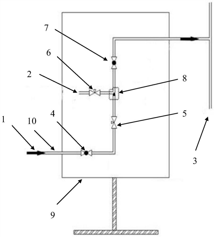
[0045] The chemical gas sampling equipment of the present invention comprises a sampling box 9 , a sample tube 10 , a sampling tube 2 and a recovery tube 3 .

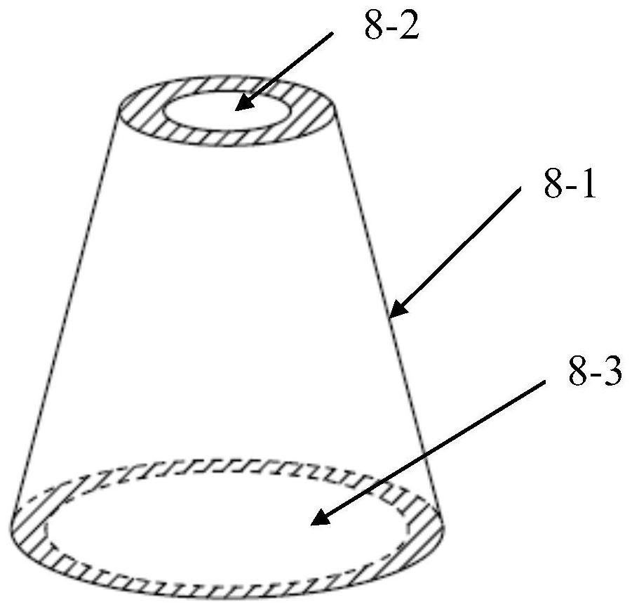
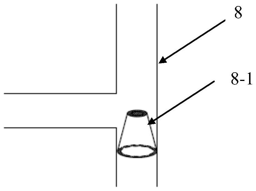
[0046] One end of the sample tube 10 is provided with a process gas inlet 1, and the other end is provided with a process gas outlet, and the process gas outlet is connected to the recovery pipe 3; the sample tubes from the process gas inlet 1 to the process gas outlet are sequentially provided with first A spherical valve 4, a first needle valve 5, a self-priming three-way valve 8 and a second spherical valve 7; the self-priming three-way valve 8 i...


PUM


Abstract

The invention discloses chemical gas sampling equipment and a gas sampling method. The sampling equipment comprises a sampling box, a sample tube, a sampling tube, a spherical valve, a needle valve, a self-suction three-way valve and a recovery tube, and the chemical gas sampling equipment is formed by installing and combining the components such as the self-suction tee joint, the needle valve, the spherical valve, the sample tube, the sampling tube, the recovery tube and the sampling box, and a safe, environment-friendly, energy-saving, efficient and low-cost chemical gas sampling process is realized. According to the chemical gas sampling equipment and the gas sampling method, the conical flow control component is arranged in the three-way valve, the flow control component is of a hollow structure, the air outlet in the top is smaller than the air inlet in the bottom, and the self-suction negative pressure effect is achieved. The gas sampling method is simple to operate, the process gas is firstly replaced with the pipeline by arranging the valve and adjusting the valve, then the process gas is replaced with the gas stored in the ball bladder or the gas bag, and finally sampling is carried out. As the bladder or the air bag does not need to be squeezed forcefully in the gas replacement process, no dead angle is left in the bladder or the air bag after replacement, replacement is clean, and sampling data are accurate.

Description

technical field [0001] The invention belongs to the field of chemical gas sampling, relates to chemical gas sampling equipment, in particular to a special equipment for sampling gas under pressure and a gas sampling method. Background technique [0002] Sampling and analysis of chemical gases is very common in modern industrial production. The safety and representativeness of sampling are particularly important in the subsequent analysis process. Without the safety and representativeness of sampling, the subsequent sampling and analysis results will lose their meaning, and at the same time cannot Direct the adjustment of production parameters. [0003] The current chemical gas sampling has the following defects: [0004] 1. On-site discharge: First of all, whether the chemical gas is raw material gas or a higher-cost process gas after conversion and synthesis, if the on-site discharge is not only a waste of resources, but also an increase in cost. Secondly, since chemical ...

Claims


Application Information

Patent Timeline
Patent Type & Authority Applications(China)
IPC IPC(8): G01N1/24
CPCG01N1/2247G01N1/24
Inventor 常大顺张海涛吴乾万
Owner CHINA BLUECHEMICAL
Why Eureka
Try Eureka