Eureka AIR delivers breakthrough ideas for toughest innovation challenges, trusted by R&D personnel around the world.

A communication power distribution cabinet

A technology for communication power supply and power distribution cabinet, which is applied to substation/distribution device casings, electric components, electromechanical devices, etc., can solve the problems of dust filter not being able to filter dust, clogging of filter eyes, and easy clogging of dust filter.

Active Publication Date: 2022-07-08
GUANGZHOU POST & TELECOMM EQUIPMENT CO LTD
View PDF6 Cites 0 Cited by
  • Summary
  • Abstract
  • Description
  • Claims
  • Application Information

AI Technical Summary

Problems solved by technology

[0005] However, the applicant found in the actual use process that in order to play a good dust filtering effect in the dust filter net, the size of its filter holes is usually very small, and in practical applications, the problem of clogging of the filter holes and causing the blockage of the dust filter net is often prone to occur. It is especially common in outdoor power distribution cabinets. After the dust filter is clogged, on the one hand, it will not be able to filter dust normally; , it may also cause the cabinet to fail to dissipate heat normally and cause circuit components to burn out
After the dust filter is clogged, it is difficult to find and deal with it in time. Usually, it can only be found when the temperature of the power distribution cabinet is obviously abnormal. After the discovery, it is also necessary for the staff to arrive at the scene. After the power is cut off, the dust filter is taken out for cleaning or replacement. The maintenance process very cumbersome
[0006] To sum up, in the prior art, the dust filter at the heat dissipation hole of the power distribution cabinet has the defect that it is easy to be blocked and difficult to handle after being blocked.

Method used


Image

  • A communication power distribution cabinet
  • A communication power distribution cabinet
  • A communication power distribution cabinet

Examples


Embodiment Construction

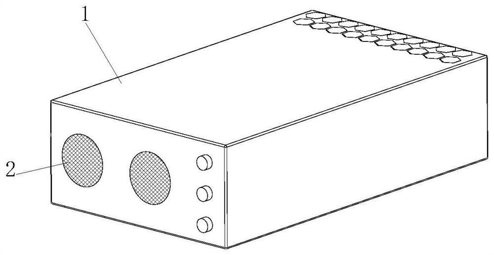
[0038] like Figure 1-Figure 4As shown, a communication power distribution cabinet according to the present invention includes a cabinet body 1, the cabinet body 1 has a square box-like structure, and the interior of the cabinet body 1 is hollow to form an installation cavity for installing circuit components. The side of the cabinet body 1 is provided with a heat dissipation hole which communicates with the installation cavity.

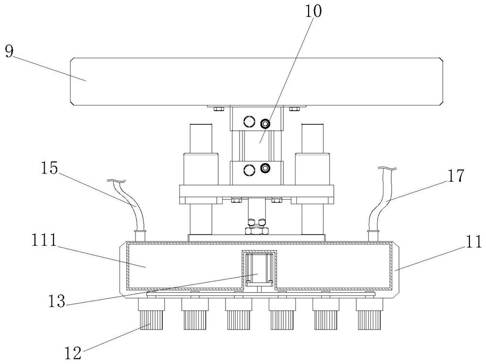
[0039] The communication power distribution cabinet also includes a cleaning mechanism arranged in the installation cavity for cleaning the dust filter 2. The cleaning mechanism specifically includes a dust sensor 3, a wind speed sensor 4, a controller 5, a driving member 6, a transmission Assembly 7 , guide member 8 , sliding seat 9 , telescopic member 10 , brush head seat 11 , brush head 12 and brush head motor 13 .

[0040] Both the dust sensor 3 and the wind speed sensor 4 are arranged on the inner side of the cooling fan, and correspond to the ...


PUM


Abstract

The invention discloses a communication power distribution cabinet, which relates to the technical field of distribution cabinets. The invention includes a cabinet body, the side of the cabinet body is provided with heat dissipation holes, the heat dissipation holes are provided with a dust filter, and a heat dissipation fan is provided on the side of the heat dissipation holes; and also includes a cleaning mechanism, and the cleaning mechanism includes a dust sensor, a wind speed sensor, Controller, driving part, transmission assembly, guide part, sliding seat, telescopic part, brush head seat, brush head and brush head motor; dust sensor and wind speed sensor are arranged on the inner side of cooling fan, dust sensor and wind speed sensor are both connected with control The guide part is arranged on the inner side of the cabinet; the sliding seat is slidably arranged on the guide part; the driving part is linked with the sliding seat through the transmission assembly; one end of the telescopic part is connected to the sliding seat, and the other end is connected to the brush head seat; The rotation is arranged on the brush head seat, and the brush head motor is linked with the brush head. The invention can automatically clean the dust filter when the dust filter is blocked, can effectively avoid the blockage of the dust filter, and is more convenient for daily maintenance.

Description

technical field [0001] The invention relates to the technical field of power distribution cabinets, in particular to a communication power distribution cabinet. Background technique [0002] Power distribution cabinets can be divided into power distribution cabinets, lighting distribution cabinets and metering cabinets. They are the final equipment of power distribution systems and are mainly used in power plants, substations, petrochemicals, metallurgical steel rolling, light industry and textiles, factories and mining enterprises. , residential quarters, etc. [0003] Due to the characteristics of many internal circuit components and long working hours, the power distribution cabinet will generate a lot of heat during continuous operation. The cabinet of the power distribution cabinet is a relatively sealed environment, and the heat generated by the circuit components is not easy to dissipate. Working for a long time will cause the circuit components to overheat and burn ...

Claims


Application Information

Patent Timeline
Patent Type & Authority Patents(China)
IPC IPC(8): H02B1/28B01D46/10B08B1/04B08B5/02B08B3/02B01D53/26H02B1/56H02B1/32H02B1/24H02K7/06
CPCH02B1/28B01D46/10B08B1/04B08B1/002B08B5/02B08B3/02B01D53/26H02B1/565H02B1/32H02B1/24H02K7/06B01D46/72B01D46/681
Inventor 黄周平
Owner GUANGZHOU POST & TELECOMM EQUIPMENT CO LTD
Why Eureka
Eureka Blog
Learn More