Gas cooler configuration integrated into heat pump chassis

a technology of gas cooler and heat pump, which is applied in the direction of domestic cooling equipment, indirect heat exchangers, lighting and heating equipment, etc., can solve the problems of compromising the efficiency of the heat pump evaporator, and achieve the effect of minimizing the negative impact of the gas cooler on the evaporator and the system performan

Inactive Publication Date: 2006-04-20
CARRIER CORP
View PDF7 Cites 10 Cited by
  • Summary
  • Abstract
  • Description
  • Claims
  • Application Information

AI Technical Summary

Benefits of technology

[0006] The dimensions of the gas cooler are designed to minimize the impact that the gas cooler has on the cooling capacity of the evaporator by reducing the amount of air flow that the gas cooler blocks. This is achieved by optimizing the way to package the gas cooler, for example, by reducing the depth that the gas cooler extends into the chassis cavity. As a result, the height and / or width of the gas cooler is increased compared to other similar volume gas coolers while still providing comparable water heating capacity. As a result, a shorter length of the evaporator coils is affected by the blocked airflow.
[0008] In an example shown, four sides of the gas cooler are located proximate to the spaced apart horizontal and vertical supports providing a gas cooler having a thin profile that does not extend very deeply into the chassis cavity. Additionally, the gas cooler may provide one of the exterior sides of the chassis, eliminating a separate wall used in the prior art. Preferably, the depth of the gas cooler is less than the width and / or the height. Also, the chassis may incorporate one or more guides so that the thin-profiled inventive gas cooler may be removably received within a portion of the housing preferably proximate to an outer wall of the chassis.
[0009] Accordingly, the present invention provides an improved gas cooler and chassis arrangement that minimizes the negative impact the gas cooler has on the evaporator and system performance by blocking the airflow to the evaporator.

Problems solved by technology

As a result, the gas cooler blocks and significantly inhibits the air flow through the chassis compromising the efficiency of the heat pump evaporator and ability of the evaporator to perform desirably under the various operating conditions.

Method used


Image

  • Gas cooler configuration integrated into heat pump chassis
  • Gas cooler configuration integrated into heat pump chassis

Examples


Embodiment Construction

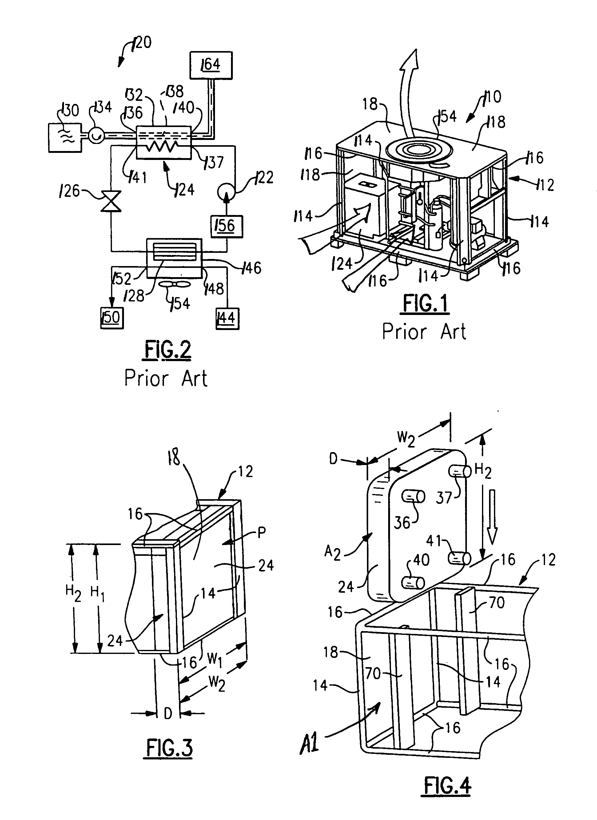
[0015]FIGS. 1 and 2 depict prior art heat pump systems. FIG. 1 illustrates a heat pump water heater 110 having a chassis 112 constructed from multiple vertical 114 and horizontal 116 supports forming a box-like structure for housing the components of the heat pump system 110. Walls 118 are typically supported on the supports 114 and 116 to enclose the components and protect them from the exterior environment. However, the walls 118 are also considered vertical and horizontal supports and together define an outer shape. One of the walls 118 supports a fan 154 for moving air through the chassis to ensure desired operation of an evaporator located within. Maximizing the air flow through the evaporator enables desired heat pump performance during extreme operating conditions.

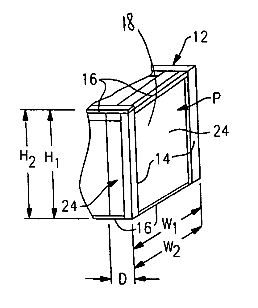
[0016] As can be seen in FIG. 1, the prior art gas cooler 124 extends a considerable depth into the cavity of the chassis 112 such that it obstructs a significant amount of air flow inhibiting the desired operation...


PUM


Abstract

A thin-profiled gas cooler and chassis suitable for a transcritical heat pump water heater are provided. The heat pump system includes a chassis for supporting such system components as a gas cooler and evaporator. The dimensions of the gas cooler are designed to minimize the impact that the gas cooler has on the cooling capacity of the evaporator by reducing the amount of air flow that the gas cooler blocks. This is achieved by reducing the depth that the gas cooler extends into the chassis cavity. As a result, the height and / or width of the gas cooler is increased compared to other similar volume gas coolers is providing comparable water heating capacity.

Description

BACKGROUND OF THE INVENTION [0001] The present invention relates to a gas cooler and chassis for a transcritical heat pump water heater. [0002] One type of transcritical heat pump water heater uses a heat pump cycle that utilizes CO2 as the working fluid. The heat pump may be located indoors or on the exterior of a building, for example, mounted on a roof top of a building. Numerous components are located within a chassis that supports the components, which includes for example a compressor, a gas cooler, an expansion device, an evaporator, an accumulator, and other various components. [0003] In a CO2 heat pump water heating system, super critical CO2 rejects heat in the gas cooler to water, and sub-critical CO2 absorbs heat in the evaporator from the outdoor air. The heat pump system must operate desirably under a wide range of conditions. For example, the outdoor air temperature may vary from −10° F. in the winter to the 120° F. in the summer. A draft fan is usually used to force ...

Claims


Application Information

Patent Timeline
Patent Type & Authority Applications(United States)
IPC IPC(8): F25D19/00F25B39/04
CPCF25B9/008F25B2309/061F25B2339/047F25D23/006F28D2021/0073
Inventor ZHANG, LILIRIOUX, WILLIAM A.
Owner CARRIER CORP
Why Eureka
Try Eureka