

Surgical instrument cleaning equipment for obstetrics and gynecology department
A technique for surgical instruments and cleaning equipment, which is applied in the directions of cleaning methods using liquids, chemical instruments and methods, cleaning methods and utensils, etc., can solve the problems of insufficient cleaning and harm to the human body, etc. The effect of facilitating subsequent operations
- Summary
- Abstract
- Description
- Claims
- Application Information
AI Technical Summary
Problems solved by technology
Method used
Image


Examples
Embodiment 1
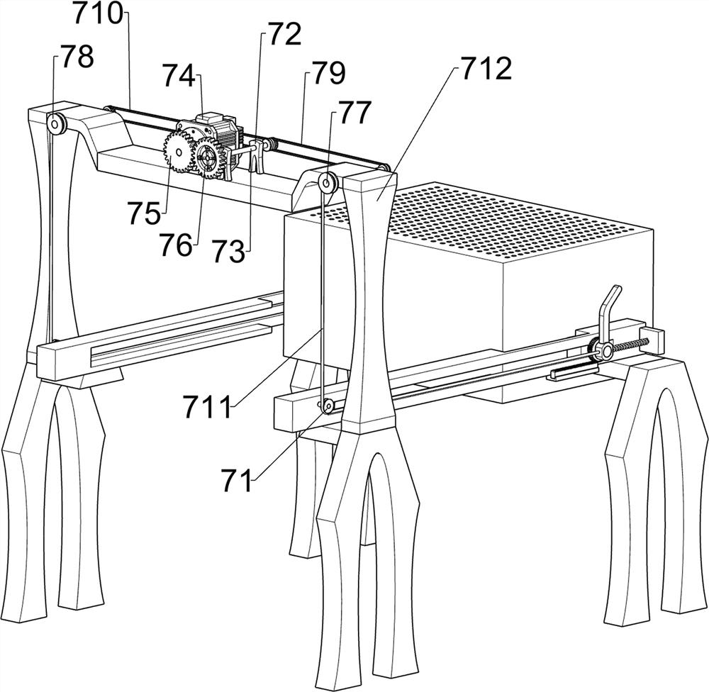
[0095] A kind of obstetrics and gynecology surgical instrument cleaning equipment, such as figure 1 As shown, it includes a base plate 1, a frame 2, a carrying mechanism 3 and a cleaning mechanism 4. Two frames 2 are connected to the front and rear sides of the upper part of the base plate 1, and two frames 2 are connected between the upper sides of the two frames 2 on the front and rear sides. A cleaning mechanism 4 is arranged between the carrying mechanism 3 and the left frame 2 .
[0096] When the device needs to be used, the user can pour clean water into the cleaning mechanism 4, push the carrying mechanism 3 to the left, and when the carrying mechanism 3 moves to the left, the carrying mechanism 3 will reverse through the cooperation between the components of the carrying mechanism 3 , at this time, the user can place the medical device in the carrying mechanism 3 to achieve the purpose of transporting the medical device and facilitate the subsequent cleaning operation,...
Embodiment 2
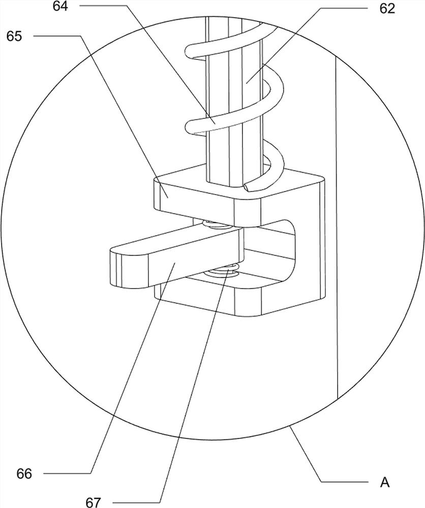
[0098] On the basis of Example 1, such as figure 2 As shown, the carrying mechanism 3 includes a first guide plate 31, a fixed rack 32, a first spring 33, a placement frame 34, a first fixed shaft 35, a limit block 36, a first gear 37 and a first wedge rod 38, A first guide plate 31 is connected between the upper sides of the two racks 2 on the front and rear sides, and a fixed rack 32 is connected to the lower side of the first guide plate 31. The first guide plate 31 slides and is connected with the first guide plate 31 in a rotational manner. One fixed shaft 35, the inside of the first fixed shaft 35 is connected with a limit block 36, and the inside of the limit block 36 is connected with a placement frame 34, and the first fixed shaft 35 is rotatably connected with a first wedge-shaped rod 38. A first spring 33 and a telescopic rod are connected between the right side of the wedge bar 38 and the first guide plate 31 , and a first gear 37 is connected on the first fixed s...
PUM
 Abstract
Description
Claims
Application Information