Automatic assembling machine for tiny headless screws and nuts

An automatic assembly machine and headless screw technology, applied in the direction of metal processing, metal processing equipment, manufacturing tools, etc., can solve the problems of electroplating layer damage, large screw nut size, low precision requirements, etc., to achieve less scratches, high assembly High pass rate and high precision

Inactive Publication Date: 2021-06-04
深圳市驰速自动化设备有限公司
View PDF16 Cites 2 Cited by
  • Summary
  • Abstract
  • Description
  • Claims
  • Application Information

AI Technical Summary

Problems solved by technology

[0003] The general screw nuts in the prior art are relatively large in size, do not require high precision, and have a relatively simple structure. Therefore, most of the automatic assembly machines for tiny headless screw nuts are lacking on the market, and the minimum assembly size of the screw nut assembly also reaches M3 and above. , the automatic assembly of micro-miniature headless screw nuts cannot be realized. In addition, the existing assembly machine will damage the electroplating layer of the product surface during use. Therefore, we propose an automatic assembly machine for micro-miniature headless screw nuts to solve the above problems

Method used


Image

  • Automatic assembling machine for tiny headless screws and nuts
  • Automatic assembling machine for tiny headless screws and nuts
  • Automatic assembling machine for tiny headless screws and nuts

Examples


Embodiment Construction

[0035] The following will clearly and completely describe the technical solutions in the embodiments of the present invention with reference to the accompanying drawings in the embodiments of the present invention. Obviously, the described embodiments are only some, not all, embodiments of the present invention. Based on the embodiments of the present invention, all other embodiments obtained by persons of ordinary skill in the art without making creative efforts belong to the protection scope of the present invention.

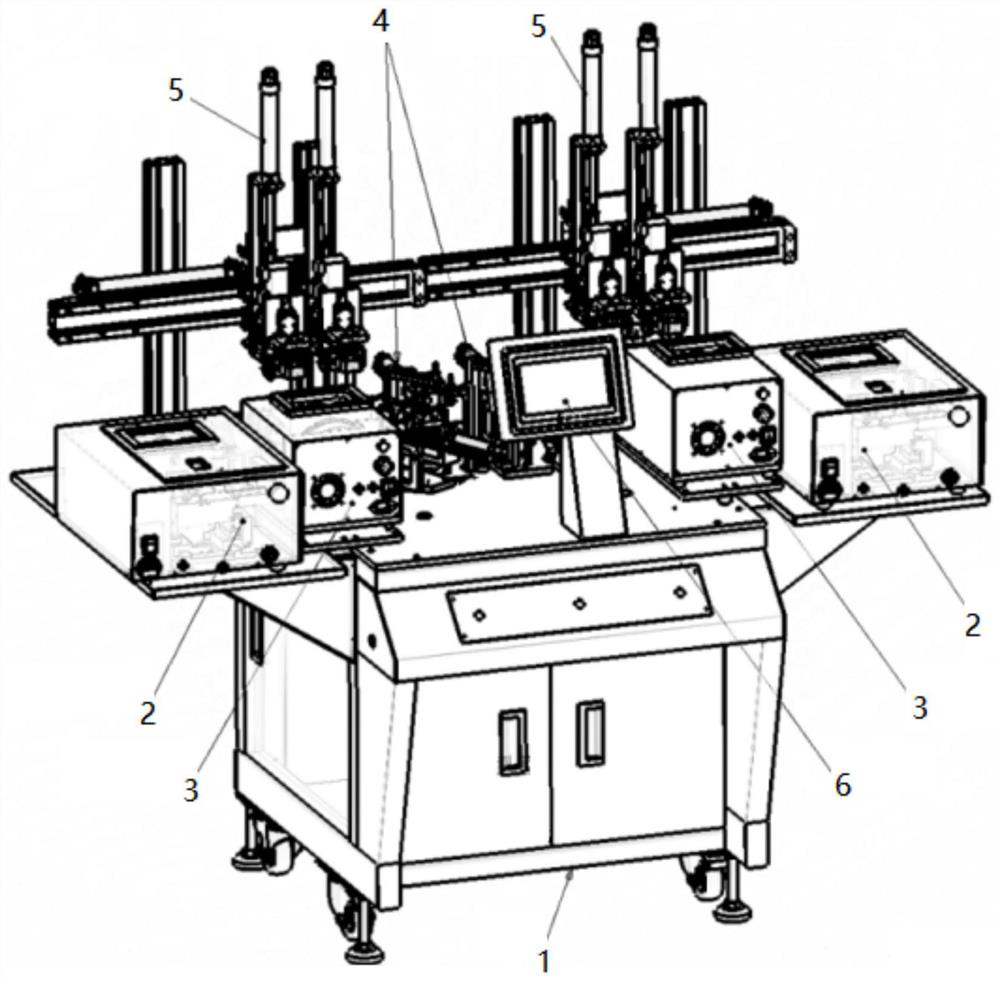
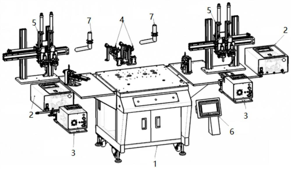
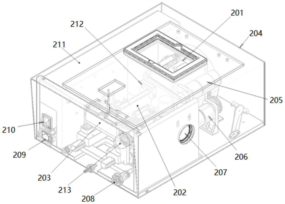
[0036] see Figure 1-5 , an automatic assembly machine for tiny headless screw nuts, including a frame 1, a screw supply mechanism 2 is arranged on the frame 1, and it is used for screw feeding. In this embodiment, the screw supply mechanism 2 is externally provided with a feeding machine housing 204, the top of the feeder housing 204 is provided with a screw material storage box 201, the inside of the feeder housing 204 is provided with a screw linear feeding...


PUM


Abstract

The invention relates to the technical field of automatic assembling machines, and discloses an automatic assembling machine for tiny headless screws and nuts. The machine comprises a rack, and the rack is provided with a screw feeding mechanism for screw feeding, a nut feeding mechanism, a screw grabbing mechanism, a screwing mechanism and a touch screen. The nut feeding mechanism is located at one side of the screw feeding mechanism and used for feeding nuts; the screw grabbing mechanism is located at one side of the nut feeding mechanism and used for grabbing screws; and the screwing mechanism is located at the rear side of the screw feeding mechanism and the nut feeding mechanism and used for assembling the screws and the nuts, and the touch screen is located at the front sides of the screw feeding mechanism and the nut feeding mechanism and used for controlling the assembling machine to start. According to the automatic assembling machine for the tiny headless screws and nuts, accurate butt joint of the screws and the nuts is achieved through an accurate screw grabbing and aligning mechanism, namely three sets of air cylinders are used for grabbing, aligning and limiting, and the situation that in the prior art, a claw clamp and spring integrated screwdriver bit cannot meet accurate alignment of the tiny screws and nuts, and consequently normal use cannot be achieved is avoided.

Description

technical field [0001] The invention relates to the technical field of automatic assembly machines, in particular to an automatic assembly machine for tiny headless screw nuts. Background technique [0002] Automatic assembly machine, also known as automatic assembly machine, refers to the combination of several parts of the product through tight fit, buckle, screw connection, bonding, riveting, welding, etc. to obtain predetermined dimensional accuracy and function. Finished (semi-finished) machinery and equipment. [0003] The general screw nuts in the prior art are relatively large in size, do not require high precision, and have a relatively simple structure. Therefore, most of the automatic assembly machines for tiny headless screw nuts are lacking on the market, and the minimum assembly size of the screw nut assembly also reaches M3 and above. , the automatic assembly of tiny headless screw nuts cannot be realized. In addition, the existing assembly machines will dama...

Claims


Application Information

Patent Timeline
Patent Type & Authority Applications(China)
IPC IPC(8): B23P19/06
CPCB23P19/069B23P19/001B23P19/006
Inventor 刘贤海刘君子
Owner 深圳市驰速自动化设备有限公司
Why Eureka
Try Eureka