
Clamping device and system, control method and bar clamping and conveying method

A technology of clamping device and fastener, applied in the field of clamping device and bar clamping and conveying, can solve problems such as affecting the service life of the tool, product quality problems, not being cut off, etc., to reduce the use and maintenance costs, The effect of avoiding uneven chip thickness and eliminating joint gaps

Active Publication Date: 2021-06-04
BAOSTEEL SPECIAL STEEL SHAOGUAN CO LTD
View PDF9 Cites 0 Cited by
  • Summary
  • Abstract
  • Description
  • Claims
  • Application Information

AI Technical Summary

Problems solved by technology

In order to ensure that the axis of the bar and the center of the cutter wheel are always consistent during the pinching process, the existing clamping mechanism generally uses two push rods to clamp the bar from two directions, but the movement of the two push rods cannot Always keep synchronous, and at the same time, after the push rod has been used for a long time, the movement synchronization will also have errors, which makes the axis of the bar deviate from the center of the rotating cutter wheel, and it is easy to cause chip thickness to vary or have irregularities on the surface of the bar during the chip cutting process. If the bar is not cut off, and the bar after being chipped is prone to ellipse, it will cause product quality problems, and it will also affect the service life of the rotary cutter wheel, resulting in an increase in the use and maintenance costs of the peeling equipment.

Method used


Image

  • Clamping device and system, control method and bar clamping and conveying method
  • Clamping device and system, control method and bar clamping and conveying method
  • Clamping device and system, control method and bar clamping and conveying method

Examples


Embodiment Construction

[0039] In order to make the purposes, technical solutions and advantages of the embodiments of the present application clearer, the technical solutions in the embodiments of the present application will be clearly and completely described below in conjunction with the drawings in the embodiments of the present application. Obviously, the described embodiments It is a part of the embodiments of this application, not all of them. The components of the embodiments of the application generally described and illustrated in the figures herein may be arranged and designed in a variety of different configurations.

[0040] Accordingly, the following detailed description of the embodiments of the application provided in the accompanying drawings is not intended to limit the scope of the claimed application, but merely represents selected embodiments of the application. Based on the embodiments in this application, all other embodiments obtained by persons of ordinary skill in the art w...


PUM


Abstract

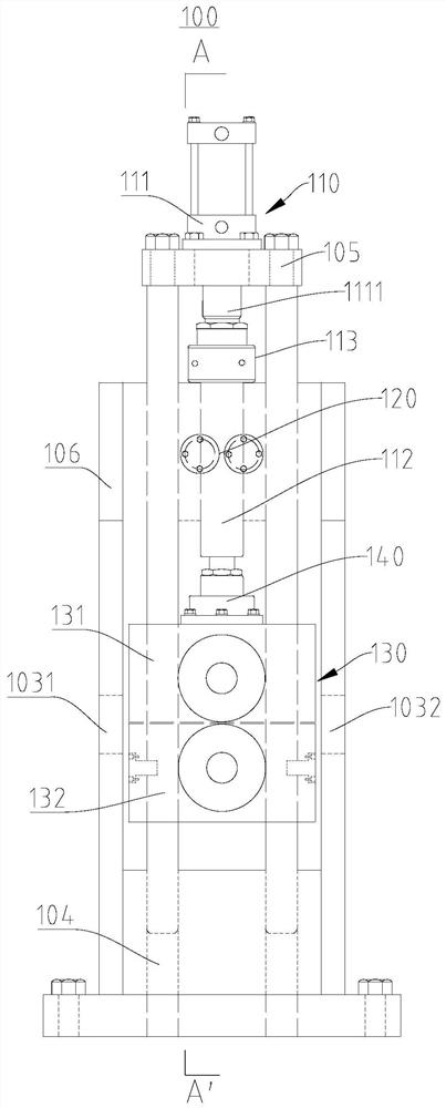
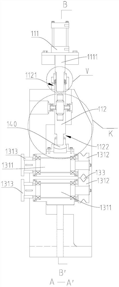
The invention relates to the field of machining, in particular to a clamping device and system, a control method and a bar clamping and conveying method. According to the clamping device, when a boosting rod is driven by a driving piece to move in the first direction, a first pressing roller support is driven to move in the first direction, and a transmission assembly drives a second pressing roller support to move in the opposite direction, so that the first pressing roller support and the second pressing roller support get close to each other to reduce a clamping space or get away from each other to expand the clamping space; an adjusting mechanism elastically acts on the driving piece and the boosting rod in the axial direction so that a connecting gap can be eliminated, precision is guaranteed, and accumulative errors are avoided; and the first pressing roller support is connected to the boosting rod in a floating mode such that a large displacement floating compensation function can be achieved, the problem of deviation such as vertical shaking in the workpiece conveying process is solved, and it is guaranteed that the axes of clamped bars and the center of a rotating cutter wheel are always kept consistent in the machining process such that the product quality problems that in the cutting process of the surfaces of the bars, the cutting thicknesses are different or some bars are not cut off and the like can be solved.

Description

technical field [0001] The present application relates to the field of processing, in particular, to a clamping device, a system and a control method, and a clamping and conveying method for bars. Background technique [0002] During the peeling and chipping process of the bar, a layer of skin parallel to the axis of the bar is usually cut off by rotating the cutter wheel along the diameter of the bar. [0003] At present, the above operations are generally completed by moving the bar through a fixed rotating cutter wheel, that is to say, the bar is first fixed by the clamping device, and then the bar and the clamping device are sent to the rotating cutter wheel by the transfer mechanism. Make chips. In order to ensure that the axis of the bar and the center of the cutter wheel are always consistent during the pinching process, the existing clamping mechanism generally uses two push rods to clamp the bar from two directions, but the movement of the two push rods cannot Kee...

Claims


Application Information

Patent Timeline
IPC IPC(8): B23Q3/00B23Q7/00
CPCB23Q3/00B23Q7/00
Inventor 杨家满夏宏基刘海鹏陈听雨廖子东刘沫夏容臻芹蔡国强戴坚辉
Owner BAOSTEEL SPECIAL STEEL SHAOGUAN CO LTD
Learn More