Mold cavity cooling water channel structure combining circulating water channel and spiral water channel

A technology of cooling water channel and circulating water channel, which is applied in the field of mold cavity cooling water channel structure, can solve the problems of uneven circumferential cooling and uneven cooling of the outer surface temperature of the preform, and achieve the effect of improving cooling uniformity and solving differences

Pending Publication Date: 2021-06-04
SOUTH CHINA UNIV OF TECH +1
View PDF0 Cites 0 Cited by
  • Summary
  • Abstract
  • Description
  • Claims
  • Application Information

AI Technical Summary

Problems solved by technology

[0002] At present, the cavity cooling water channel structure used for fast multi-cavity PET (polyethylene terephthalate) preform molds is generally a spiral water channel. When assembled with the cavity clamping ring, it is necessary for deep cooling In the transition section of the preform, the cross-sectional width of the first water channel of the general cavity channel will be nearly double or more than that of other water channels, which will cause the flow rate of the cooling liquid in the first wate

Method used


Image

  • Mold cavity cooling water channel structure combining circulating water channel and spiral water channel
  • Mold cavity cooling water channel structure combining circulating water channel and spiral water channel
  • Mold cavity cooling water channel structure combining circulating water channel and spiral water channel

Examples


Embodiment

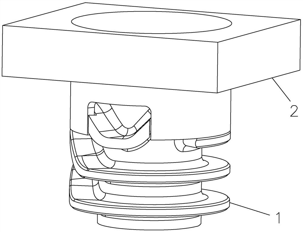
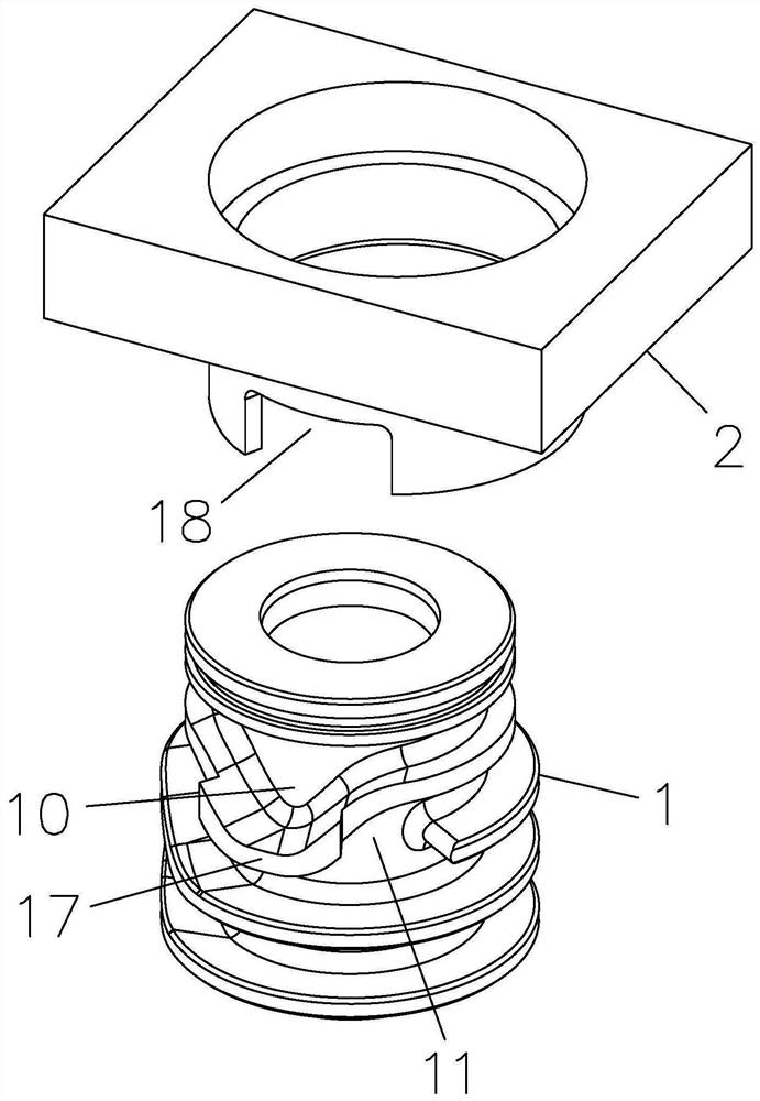
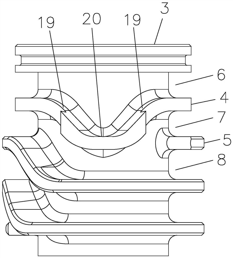
[0024] like Figure 1 to Figure 5 As shown, this embodiment discloses a mold cavity cooling waterway structure in which a circulating waterway and a spiral waterway are combined, including a mold body 3, a first rib 4 and a second rib 5, and the mold body 3 is provided with a The molding cavity for bottle preform molding, the first reinforcing rib 4 and the second reinforcing rib 5 are distributed on the outer wall of the mold body 3 at a certain distance, and the first reinforcing rib 4 surrounds the outer wall of the mold body 3 The outer wall, the second reinforcing rib 5 spirally surrounds the outer wall of the mold body 3, the first reinforcing rib 4 is distributed at a certain distance from the end of the mold body 3 to form a first circulating water tank 6, and the first reinforcing rib 4 A reinforcing rib 4 and the second reinforcing rib 5 are distributed at a certain distance to form a second circulation water tank 7, and the second reinforcing rib 5 spirally surround...


PUM

PropertyMeasurementUnit
Angleaaaaaaaaaa

Abstract

The invention discloses a mold cavity cooling water channel structure combining a circulating water channel and a spiral water channel. The mold cavity cooling water channel structure comprises a mold body, a first reinforcing rib and a second reinforcing rib, a forming cavity used for bottle blank forming is formed in the mold body, and the first reinforcing rib and the second reinforcing rib are distributed on the outer wall of the mold body at a certain interval; and the first reinforcing rib surrounds the outer wall of the mold body, the second reinforcing rib spirally surrounds the outer wall of the mold body, the first reinforcing rib and the end of the mold body are distributed at a certain interval to form a first circulation water tank, and the first reinforcing rib and the second reinforcing rib are distributed at a certain interval to form a second circulation water tank. By means of the annular flowing mode of cooling liquid in the first circulation water tank and the second circulation water tank, the cross sections and the flow speeds of the water tanks in a cooling water channel are basically equal, the difference problem of the flow speeds of the cooling liquid in the first water tank of the mold cavity and the flow speeds of the cooling liquid in other follow-up water tanks is solved, and the axial cooling uniformity of the cooling water channel and the circumferential cooling uniformity of the first tank are improved.

Description

technical field [0001] The invention relates to the technical field of mold cavity cooling water channel structure, in particular to a mold cavity cooling water channel structure in which a circulating water channel and a spiral water channel are combined. Background technique [0002] At present, the cavity cooling water channel structure used for fast multi-cavity PET (polyethylene terephthalate) preform molds is generally a spiral water channel. When assembled with the cavity clamping ring, it is necessary for deep cooling In the transition section of the preform, the cross-sectional width of the first water channel of the general cavity channel will be nearly double or more than that of other water channels, which will cause the flow rate of the cooling liquid in the first water channel to be compared with that of the other water channels. The other tanks should be lowered by half or more, which will cause uneven cooling along the axial direction. At the same time, beca...

Claims


Application Information

Patent Timeline
IPC IPC(8): B29C33/04B29C49/48
CPCB29C33/04B29C49/4823B29C2033/042B29C2049/4825
Inventor 胡青春陈境钰谢国基姜晓平梁灿棉罗国泉卢佳
Owner SOUTH CHINA UNIV OF TECH
Why Eureka
Try Eureka