Unstacking mechanism with radio frequency identifying function
A technology of radio frequency identification and palletizing, which is applied in the field of depalletizing mechanism, which can solve the problems that the equipment needs manual assistance, the space occupied by the equipment is large, and the efficiency of storage usage is reduced, so as to reduce the manual operation, improve the degree of automation, and occupy more space. small space effect
- Summary
- Abstract
- Description
- Claims
- Application Information
AI Technical Summary
Problems solved by technology
Method used
Image


Examples
Embodiment 1
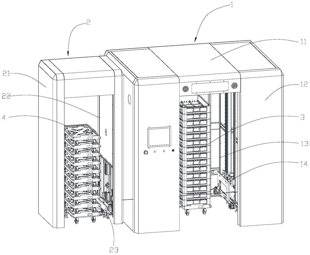
[0036] Embodiment 1: The depalletizing mechanism with radio frequency identification function of this embodiment includes a turnover box depalletizing device 1, a pallet truck depalletizing device 2 and a fork device 5; the turnover case depalletizing device 1 and pallet truck depalletizing device 2 are arranged side by side.
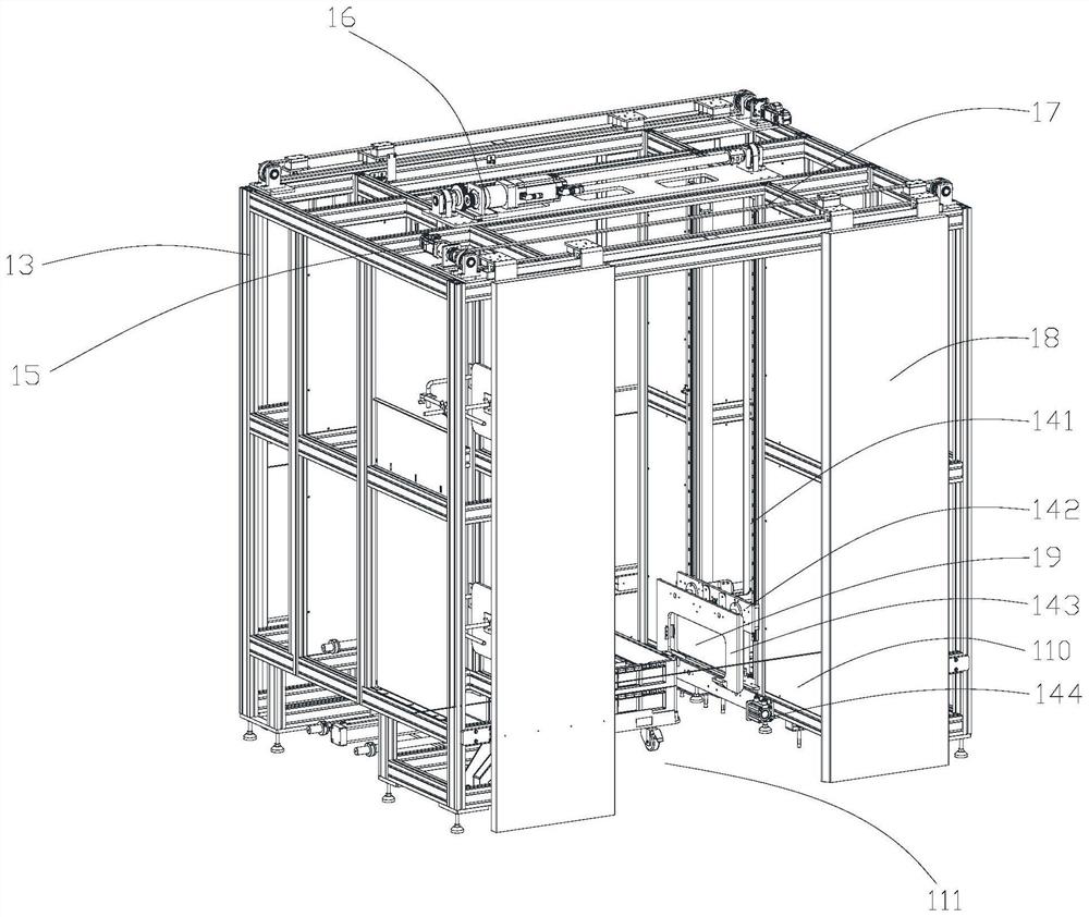
[0037] The turnover box depalletizing device 1 includes a radio frequency door assembly 11, a first frame assembly 13, a first cover body 12 that is arranged outside the first frame assembly 13, and is arranged on the first frame assembly. The shield door 18 on 13, the radio frequency identification assembly arranged on the inner wall of the first frame assembly 13, the first clamping assembly 14 arranged on the inner wall of the first frame assembly 13, and the first clamping assembly 14 for driving the first The first drive assembly 16 of the clamping assembly 14 .
[0038] The opposite sides of the first cover body 12 are provided with inlets and ou...
PUM
 Abstract
Description
Claims
Application Information
 - R&D
- Intellectual Property
- Life Sciences
- Materials
- Tech Scout
- Unparalleled Data Quality
- Higher Quality Content
- 60% Fewer Hallucinations
Browse by: Latest US Patents, China's latest patents, Technical Efficacy Thesaurus, Application Domain, Technology Topic, Popular Technical Reports.
© 2025 PatSnap. All rights reserved.Legal|Privacy policy|Modern Slavery Act Transparency Statement|Sitemap|About US| Contact US: help@patsnap.com