Method for reducing filling coefficient of cast-in-place pile in ultra-deep silt geology

A technology of filling coefficient and cast-in-place piles, which is applied in excavation, sheet pile walls, construction, etc., can solve problems such as excessive collapse, excessive concrete outflow, and affecting the construction range of foundation pits, and achieve the goal of reducing the amount of use and reducing the size Effect

Inactive Publication Date: 2021-06-04
CHINA 19TH METALLURGICAL CORP
View PDF6 Cites 1 Cited by
  • Summary
  • Abstract
  • Description
  • Claims
  • Application Information

AI Technical Summary

Problems solved by technology

However, in ultra-deep silt geology, the method of only using mud retaining wall and increasing the length of the casing may cause the concrete to flow to the possible silt subsidence area when pouring concrete underwater, and in severe cases, the concrete will flow out too much and cause subsidence If it is too large, it will affect the scope of foundation pit foundation construction

Method used


Image

  • Method for reducing filling coefficient of cast-in-place pile in ultra-deep silt geology
  • Method for reducing filling coefficient of cast-in-place pile in ultra-deep silt geology
  • Method for reducing filling coefficient of cast-in-place pile in ultra-deep silt geology

Examples


Embodiment Construction

[0035] In order to make the technical problems, technical solutions and beneficial effects to be solved by the present invention, the present invention will be described in further detail below with reference to the accompanying drawings and examples. It will be appreciated that the specific embodiments described herein are intended to explain the present invention and is not intended to limit the invention.

[0036] It should be noted that when the component is referred to as "fixed" or "set" or "connection" other component, it can be directly or indirectly located on the other component. The orientation or position of the instructions indicated by "upper", "lower", "horizontal", "vertical", "top", "bottom", "inside", "outside", etc. are based on the orientation or position shown by the drawings, only To facilitate description, it is not understood to be restricted to the present technology. The meaning of "multiple" is two or more, unless otherwise specifically defined. The mean...


PUM


Abstract

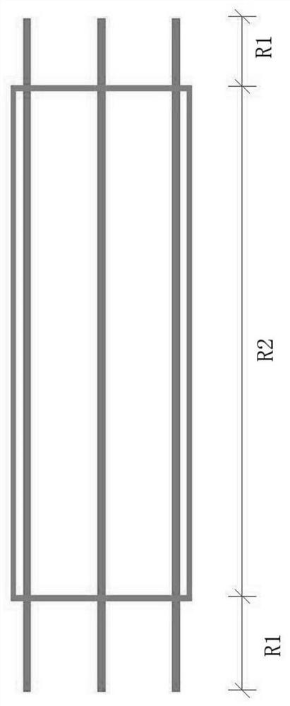
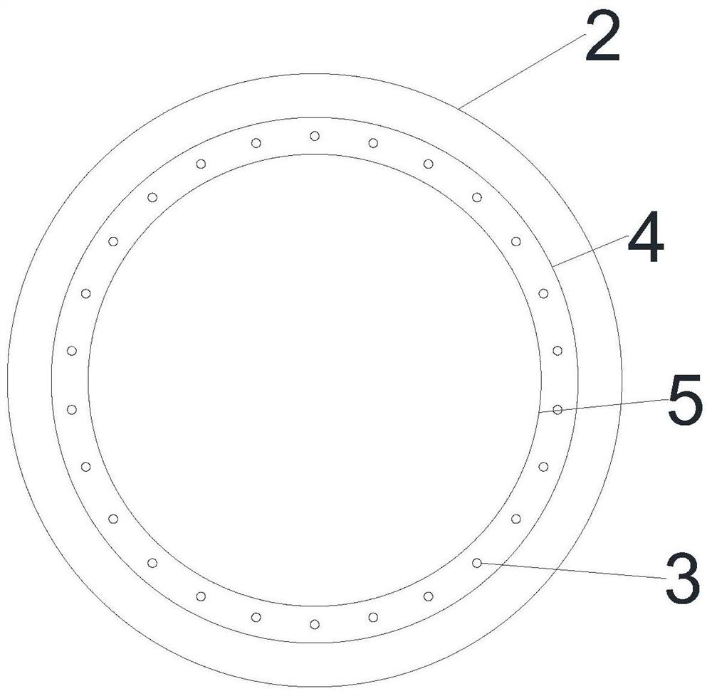
The invention discloses a method for reducing the filling coefficient of a cast-in-place pile in the ultra-deep silt geology. A manufacturing method of the cast-in-place pile comprises the steps that S1, the length of an outer cover of an iron sheet is determined according to the hole forming depth and the construction environment geology; and S2, a reinforcement cage is manufactured, the reinforcement cage comprises a positioning hoop, vertical ribs and spiral ribs from inside to outside, the reinforcement cage is formed by connecting multiple sections of unit cage bodies, all the sections of unit cage bodies are connected through welding, and the welding positions between the unit cage bodies are wrapped with iron sheets after welding is completed. The reinforcement cage of the cast-in-place pile is wrapped with the iron sheet, the flowing range of concrete is limited, the concrete is poured in the range of the reinforcement cage, the concrete poured into the reinforcement cage is prevented from flowing out, the problem that the underwater concrete flows to a sludge collapse area possibly existing during pouring is solved, the situation that the foundation pit foundation construction range is affected due to excessive collapse is avoided, and meanwhile, the hole collapse area is not filled with the concrete, so that the actual use amount of the concrete is reduced, and the filling coefficient is reduced.

Description

Technical field [0001] The present invention relates to the field of engineering construction technology, and more particularly to a method of reducing the filling pile filling coefficient in ultra-deep sludge geology. Background technique [0002] The pile is a pile of perfusion or reinforced concrete, and is divided into a mud wall into a hole according to the drilling machine of the drilling machine, and is divided into a mud wall into a hole, a hole in a hole. And the three methods of casing wall, where the mud retaining wall is a wet industry for the pile of piles. Since the main method of its hole protection is a mud wall, it is called a mud wall into a hole. [0003] It is understood that the main method of the conventional infusion pile wet operation is the main method of the mud wall, increasing the length of the cassette length. The mud removing wall is in the case of mixed liquid filled with water and bentonite and other plugs such as CMC, for the underground continuou...

Claims


Application Information

Patent Timeline
Patent Type & Authority Applications(China)
IPC IPC(8): E02D5/34E02D17/02
CPCE02D5/34E02D17/02
Inventor 张光军李涛
Owner CHINA 19TH METALLURGICAL CORP
Why Eureka
Try Eureka