

Pinfin drivepipe type reinforced heat transfer element
A heat transfer enhancement and pin-fin technology, applied in heat transfer modification, fixed tubular conduit assembly, heat exchange equipment, etc., can solve the problems of increased fluid turbulence, adverse effects of heat transfer, uneven flow distribution, etc., to achieve increased Effects of turbulence, reduction of heat transfer and flow dead zone, and increase of heat transfer area
- Summary
- Abstract
- Description
- Claims
- Application Information
AI Technical Summary
Problems solved by technology
Method used
Image

Examples
Embodiment Construction
[0024] The present invention is described in more detail below in conjunction with accompanying drawing example:
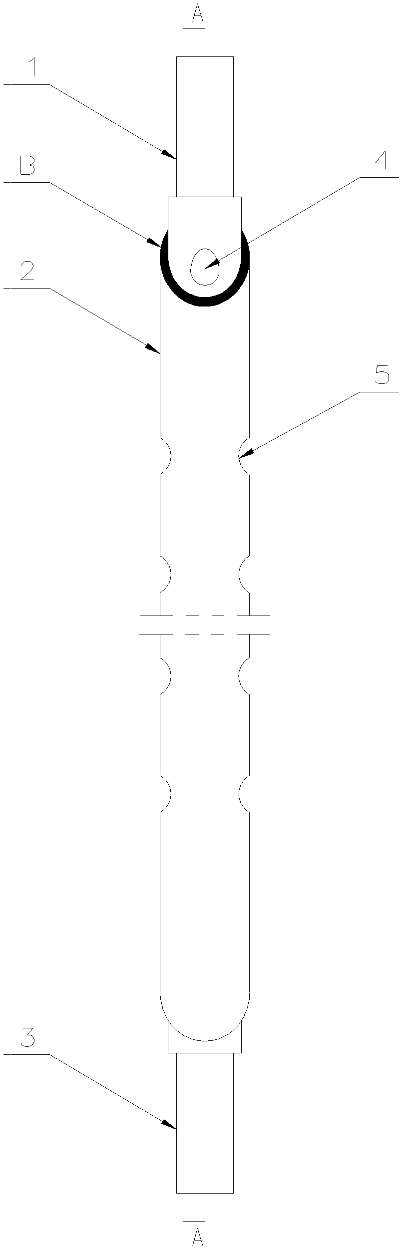
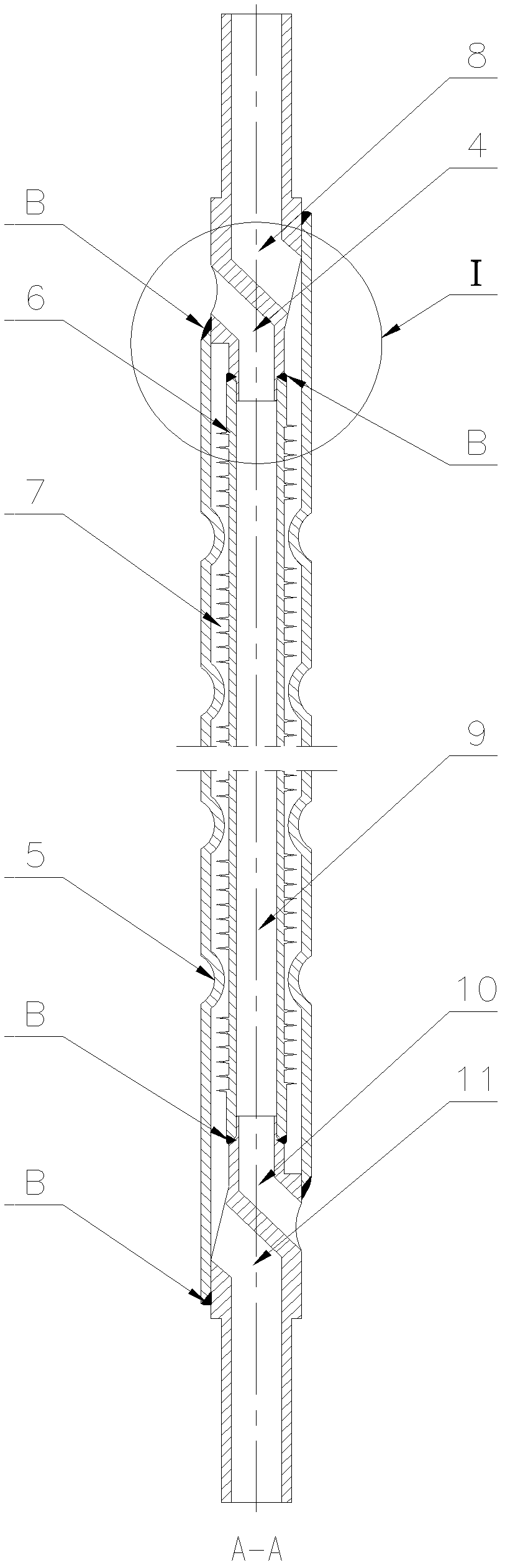
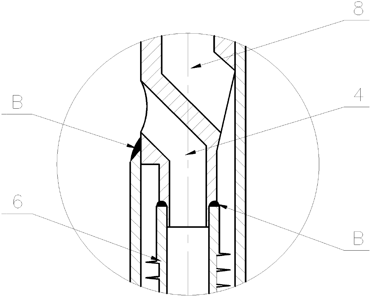
[0025] combine Figure 1~4 , a pin-fin sleeve-type enhanced heat transfer element, which is composed of a pin-fin tube, a double-channel joint and a grooved sleeve. The needle-finned tube is processed intermittently and placed inside the outer casing, and the pin-finned tube and the outer casing are connected by double-channel joints at both ends. After the pin-finned tube, the outer casing and the double-channel joint are welded, the outer casing Semi-circular grooves are rolled at positions without pin fins.
[0026] The pin-fin tube is a discontinuous pin-fin tube, and the pin-fin is directly cut on the base tube. There is no contact thermal resistance between the pin-fin and the base tube. corresponding to the location.
[0027] The initial state of the grooved sleeve is a smooth sleeve, and the grooves are rolled after the welding and installation of other...
PUM
 Abstract
Description
Claims
Application Information