
Range hood and vibration reduction control method for range hood

A technology of a range hood and a control method, which is applied in the directions of removing range hood, machine/engine, heating method, etc., can solve the problem that the range of stiffness adjustment is narrow, the number and length of raised blocks are limited, and it is difficult to effectively meet the vibration reduction of range hood. Demand and other issues to achieve the effect of meeting the vibration reduction demand

Active Publication Date: 2022-04-19
NINGBO FOTILE KITCHEN WARE CO LTD
View PDF6 Cites 0 Cited by
  • Summary
  • Abstract
  • Description
  • Claims
  • Application Information

AI Technical Summary

Problems solved by technology

[0004] But, the shock-absorbing gasket in the above-mentioned patent also has certain deficiencies. The body of the stiffness-adjusting pad of the above-mentioned shock-absorbing gasket is hollow cylindrical, and its vibration-damping adjustment function is only through some protrusions at the axial ends of the stiffness-adjusting pad. Although this structural design can obtain different stiffness values ​​for the shock-absorbing gasket, it can meet the rigidity requirements of different working conditions for the shock-absorbing gasket to a certain extent. However, due to the end of the shock-absorbing gasket Structural space is limited, and the number and length range of the protruding blocks that can be designed are limited, so the range of stiffness adjustment is still relatively narrow, especially the precise stiffness adjustment cannot be performed according to the actual use of the range hood, and it is difficult to effectively meet the requirements of various types of range hoods. Frequency damping requirements

Method used


Image

  • Range hood and vibration reduction control method for range hood
  • Range hood and vibration reduction control method for range hood
  • Range hood and vibration reduction control method for range hood

Examples


Embodiment Construction

[0045] The present invention will be further described in detail below in conjunction with the accompanying drawings and embodiments.

[0046] In describing the present invention, it should be understood that the terms "center", "longitudinal", "transverse", "length", "width", "thickness", "upper", "lower", "front", " Back", "Left", "Right", "Vertical", "Horizontal", "Top", "Bottom", "Inner", "Outer", "Clockwise", "Counterclockwise", "Axial", The orientation or positional relationship indicated by "radial", "circumferential", etc. is based on the orientation or positional relationship shown in the drawings, and is only for the convenience of describing the present invention and simplifying the description, rather than indicating or implying the referred device or element must have a particular orientation, be constructed, and operate in a particular orientation, and since the disclosed embodiments of the invention may be arranged in different orientations, these directional te...


PUM


Abstract

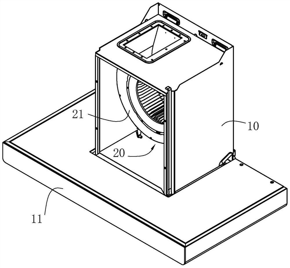
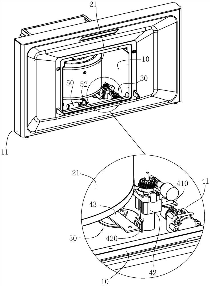
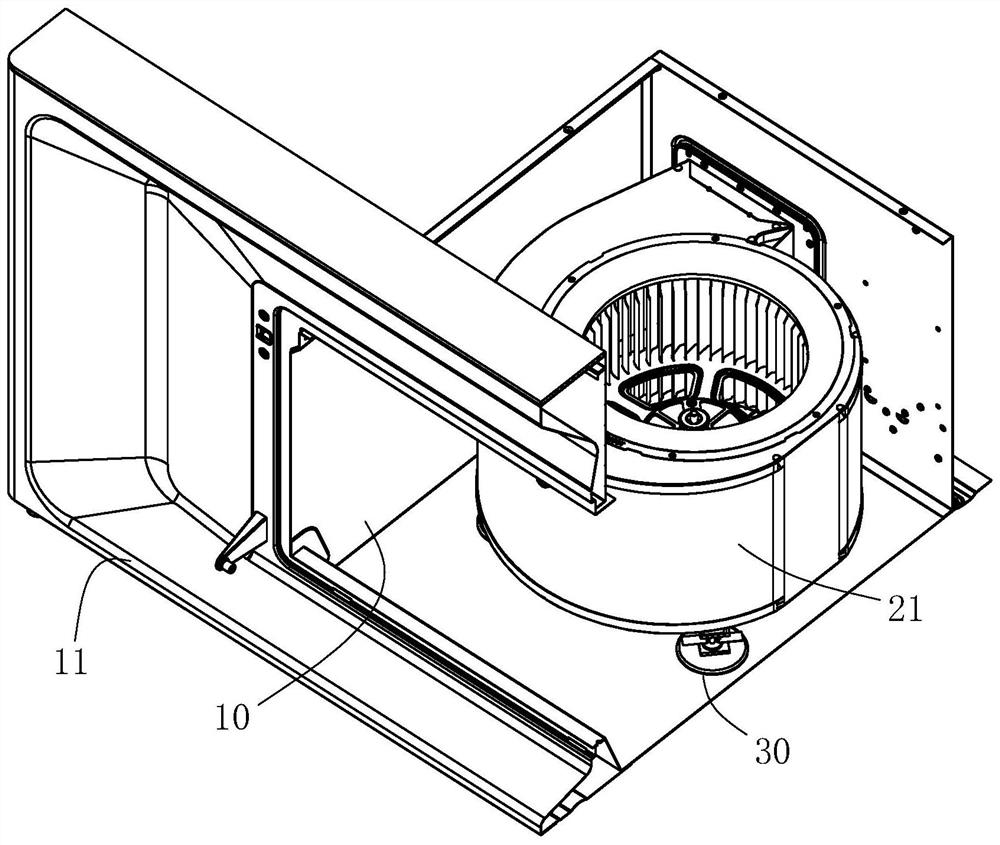
The invention relates to a range hood and a vibration reduction control method, comprising: a housing; a fan, including a volute; a vibration isolation connection device, connecting the housing and the volute; The substrate, the second substrate, the vibration-damping support column and the spring, the first substrate and the second substrate are arranged at intervals, and are connected through the vibration-damping support column, the first substrate is connected to the housing, the second substrate is connected to the volute, and the spring abutting between the first substrate and the second substrate; the adjustment mechanism includes a first drive mechanism and an adjustment plate, the power output end of the first drive mechanism is connected with the adjustment plate, and can drive the adjustment plate along the The length of the spring moves and can be inserted into the gap between any two adjacent coils of the spring to change the effective number of coils of the spring. The stiffness of the vibration isolation connection device can be adjusted, which can reduce the vibration transmission rate from the fan system to the housing to the greatest extent, and can meet the vibration reduction requirements of the range hood under various working conditions.

Description

technical field [0001] The invention relates to the technical field of range hoods, in particular to a range hood and a vibration reduction control method for the range hood. Background technique [0002] In the existing range hoods, the fan system is the part with the largest vibration, which is usually directly connected to the fan frame. Most of the components of range hoods are sheet metal parts. In the vibration transmission path, if the vibration cannot be well attenuated, the fan frame will vibrate greatly. Such as Figure 8 As shown in , if the vibration transmission rate from the fan system to the fan frame is to be effectively reduced, the stiffness K3 of the vibration isolation device needs to match the stiffness K1 of the fan system and the vibration frequency and the stiffness K2 of the fan frame, so that It has a good and targeted vibration reduction effect. However, most of the existing designs of vibration isolation and vibration reduction structures are pa...

Claims


Application Information

Patent Timeline
Patent Type & Authority Patents(China)
IPC IPC(8): F24C15/20F04D29/66
CPCF24C15/20F24C15/2021F04D29/668
Inventor 时璐璐
Owner NINGBO FOTILE KITCHEN WARE CO LTD
Learn More