Connecting structure of probe card holder

A connection structure and probe card technology, applied in the field of probe cards, can solve the problems such as the limited number of switchable and the inability to set up multiple probe cards, etc., to achieve the effect of increasing adaptability

Inactive Publication Date: 2021-06-04
哈尔滨桥晟科技发展有限公司
View PDF0 Cites 0 Cited by
  • Summary
  • Abstract
  • Description
  • Claims
  • Application Information

AI Technical Summary

Problems solved by technology

[0004] In the production process of semiconductor devices, it is necessary to visit a large number of circuit contacts in one or more devices multiple times, and move the probe card through the moving mechanism to make the probes contact with the contacts. At the same time, to match the detection process For multiple sets of contacts in the probe card, multiple probe cards need to be set, and the probe card is fixed by the holder. The holder is a polyhedron that can rotate. By setting one or more probe cards on each surface, the When switching the probe card, by rotating the holder, the corresponding probe card is rotated to the top of the semiconductor device for detection, or multiple movable platforms are set up to move the probe card to realize the connection between the probe card and different contact groups. Matching, in the prior art, in order to realize the detection of multiple sets of contacts, the exchange of probe cards is used to achieve matching, and the matching is achieved by switching different probe cards. The existing holder adopts polyhedron and mobile Due to the platform structure, multiple probe cards cannot be set, and the number of switchable probe cards is limited

Method used


Image

  • Connecting structure of probe card holder
  • Connecting structure of probe card holder
  • Connecting structure of probe card holder

Examples


Embodiment 1

[0060] This embodiment is an embodiment of a probe card holder.

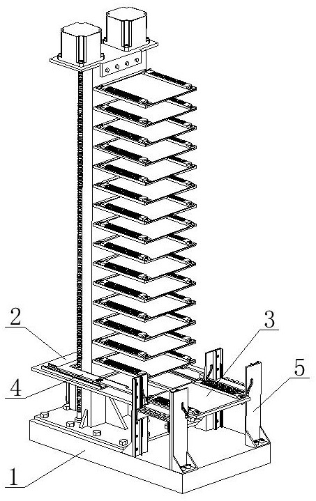
[0061] combine figure 1 As shown, a probe card holder disclosed in this embodiment includes: a base 1, a lifting platform 2, a probe card 3, a card switching structure 4 and a card connecting structure 5, and the base 1 is slidably arranged There is a lifting platform 2, and a card switching structure 4 is arranged on the lifting platform 2, and a probe card 6 is arranged on the probe card 3, and the probe card 3 is connected to the detection circuit through the card connecting structure 5;

[0062] The base 1 serves as the overall support structure and provides a vertical probe card library at the same time. The lifting table 2 moves on the probe card library to select the probe card 3, and the card switch structure 4 will The selected probe card 3 moves to the lifting platform 2, moves to the lower end of the base 1 through the lifting platform 2, and connects the probe card 3 to the detection circuit through...

Embodiment 2

[0078] This embodiment is an embodiment of a connection structure of a probe card holder. This connection structure is applied to a probe card holder disclosed in Embodiment 1 to detect whether the circuit is connected or disconnected from the probe card board 3. open.

[0079] A connection structure of a probe card holder disclosed in this embodiment includes a probe card board 3 and a card board connection structure 5, the probe card board 3 is provided with a probe card 6, and the probe card board 3. Connect with the detection circuit through the card board connection structure 5;

[0080] The card board connection structure 5 is arranged at the bottom of the device. When the lift table 2 moves to the bottom of the device with the probe card board 3, the card board connection structure 5 connects the detection circuit with the probe card 6, and the probe card 3 is carried on the lift table 2. When the card board 3 moves upwards away from the bottom of the device, the card ...

Embodiment 3

[0092] This embodiment discloses a probe card holder lifting platform based on the probe card holder disclosed in the first specific embodiment. As an alternative, the lifting platform can automatically decelerate when it falls to the bottom. At the same time, the probe card board 3 can be connected automatically.

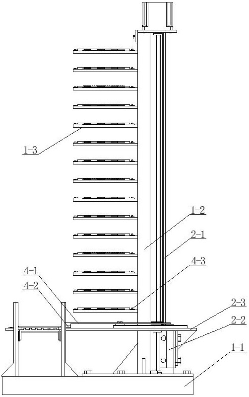
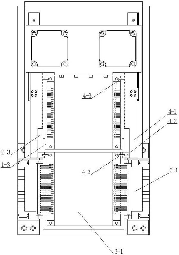
[0093] combine Figure 9 As shown, a lifting platform for a probe card holder in this embodiment includes: a lifting platform slide rail 2-1, a lifting platform slider 2-2 and a lifting platform plate 2-3, and the lifting platform sliding rail 2-1 is arranged on the back side of the vertical plate 1-2, the lift platform slider 2-2 is slidably arranged on the lift platform slide rail 2-1, and the middle of the lift platform 2-3 is provided with a via hole, and The lifting platform 2-3 is set on the vertical plate 1-2, the lifting platform 2-3 is fixedly connected with the lifting platform slider 2-2, and the via hole in the middle of the lifting platform 2-3 can ac...


PUM


Abstract

The invention belongs to the technical field of probe cards, and particularly relates to a connecting structure of a probe card holder, which comprises a probe card board and a card board connecting structure, wherein a probe card is arranged on the probe card board, the probe card board is connected with a detection circuit through the card board connecting structure, and as the connecting structure is arranged at the lower end of a lifting platform, when the lifting platform descends to the bottom, the lifting platform is in lap joint with the plug supporting plate, the plug supporting plate moves downwards, and the plug sliding block drives the connecting plug to slide inwards relative to the plug supporting plate under the guiding action of the vertical frame sliding groove until the front end of the connecting plug is inserted into the socket in the side face of the probe clamping plate. Thus, when the lifting platform descends to the bottom, the connecting plug can be automatically connected with the probe card board, and when the lifting platform leaves the bottom, the connecting plug can be automatically disconnected from the probe card board.

Description

technical field [0001] The invention belongs to the technical field of probe cards, in particular to a connection structure of a probe card holder. Background technique [0002] With the development of the semiconductor industry, more and more electronic devices are connected to the semiconductor wafer. During the manufacturing process of the semiconductor device, the probe is contacted with the metal end on the semiconductor wafer to realize a temporary electrical connection. The electrical signal of the tester is transmitted to the semiconductor device through the probe, and the tester detects the electronic device on the semiconductor wafer through the returned electrical signal. [0003] The probe card is the link between the semiconductor wafer and the tester. By integrating multiple probes on the probe card, multiple probes can be simultaneously contacted with multiple semiconductor devices on the semiconductor wafer to improve detection efficiency. . [0004] In the...

Claims


Application Information

Patent Timeline
Patent Type & Authority Applications(China)
IPC IPC(8): G01R1/073
CPCG01R1/07392
Inventor 王鸿亮
Owner 哈尔滨桥晟科技发展有限公司
Why Eureka
Try Eureka