Buried optical cable cross-connecting box capable of preventing water splashing

An optical cable junction box, splash-proof technology, applied in optics, light guides, optical components, etc., can solve the problem of the optical cable junction box splashing wet, flowing into the manhole, and the other part easily splashing into the optical cable junction box, etc. Difficulty of drainage, guaranteed use, and the effect of accelerating the cooling rate

Active Publication Date: 2021-06-04
国网河南省电力公司卫辉市供电公司
View PDF13 Cites 0 Cited by
  • Summary
  • Abstract
  • Description
  • Claims
  • Application Information

AI Technical Summary

Problems solved by technology

[0002] The buried optical cable transfer box is built in the existing communication pipeline manhole, so it can maximize the rational use of land resources and solve the problem of land shortage. The abundant groundwater in the manhole will speed up the transfer of heat, and it is also convenient for the cable transfer box However, in actual use, part of the rainwater will flow into the manhole through the through hole of the manhole cover, and the other part will flow into the manhole through the gap between the bottom of the cover and the manhole. When it is blocked, most of the rainwater will flow out from the gap between the bottom of the cover plate and the manhole. At present, the two sides of the cable transfer box are closer to the inner wall of the manhole, which makes it easy to splash on the cable transfer box. If the rainwater is too large It is also easy to make the optical cable transfer box be splashed wet. Therefore, we propose a waterproof and splash-proof underground optical cable transfer box

Method used


Image

  • Buried optical cable cross-connecting box capable of preventing water splashing
  • Buried optical cable cross-connecting box capable of preventing water splashing
  • Buried optical cable cross-connecting box capable of preventing water splashing

Examples


Embodiment Construction

[0022] The following will clearly and completely describe the technical solutions in the embodiments of the present invention with reference to the accompanying drawings in the embodiments of the present invention. Obviously, the described embodiments are only some, not all, embodiments of the present invention. Based on the embodiments of the present invention, all other embodiments obtained by persons of ordinary skill in the art without making creative efforts belong to the protection scope of the present invention.

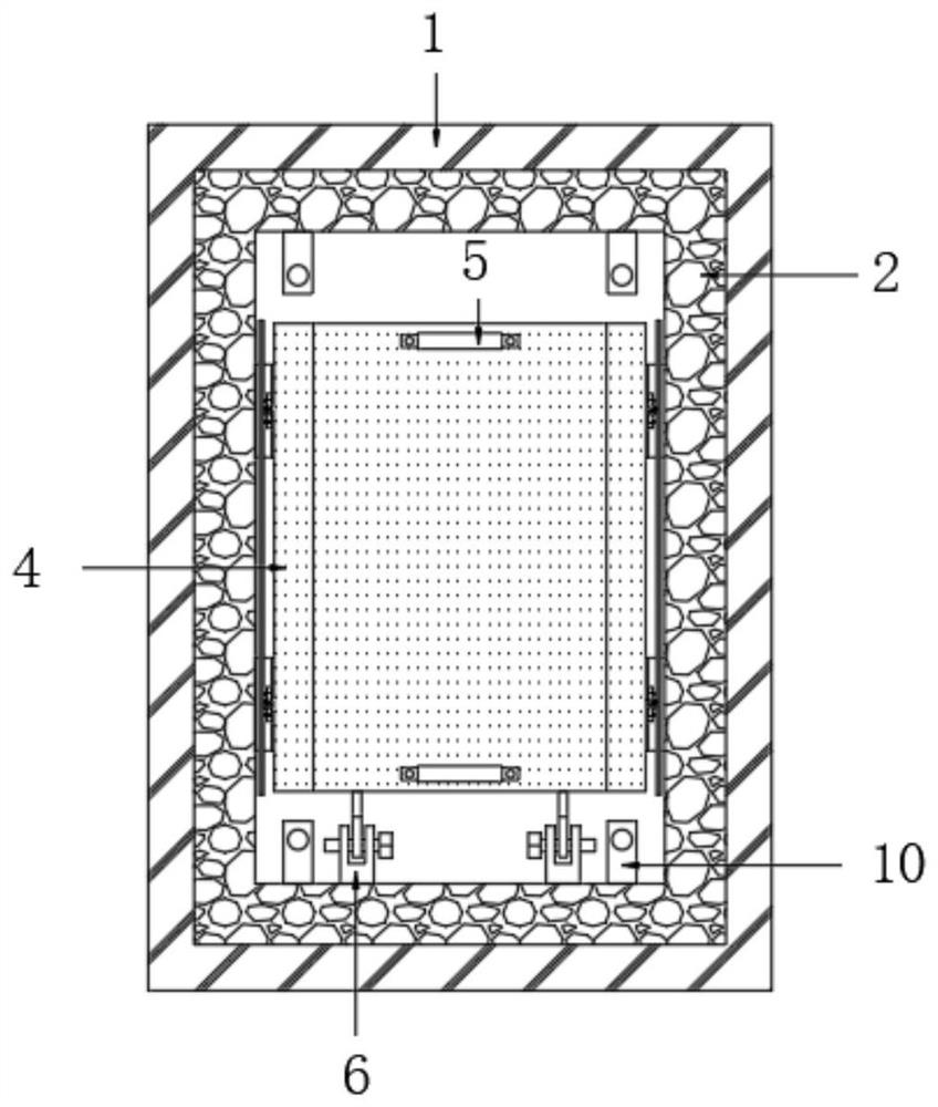
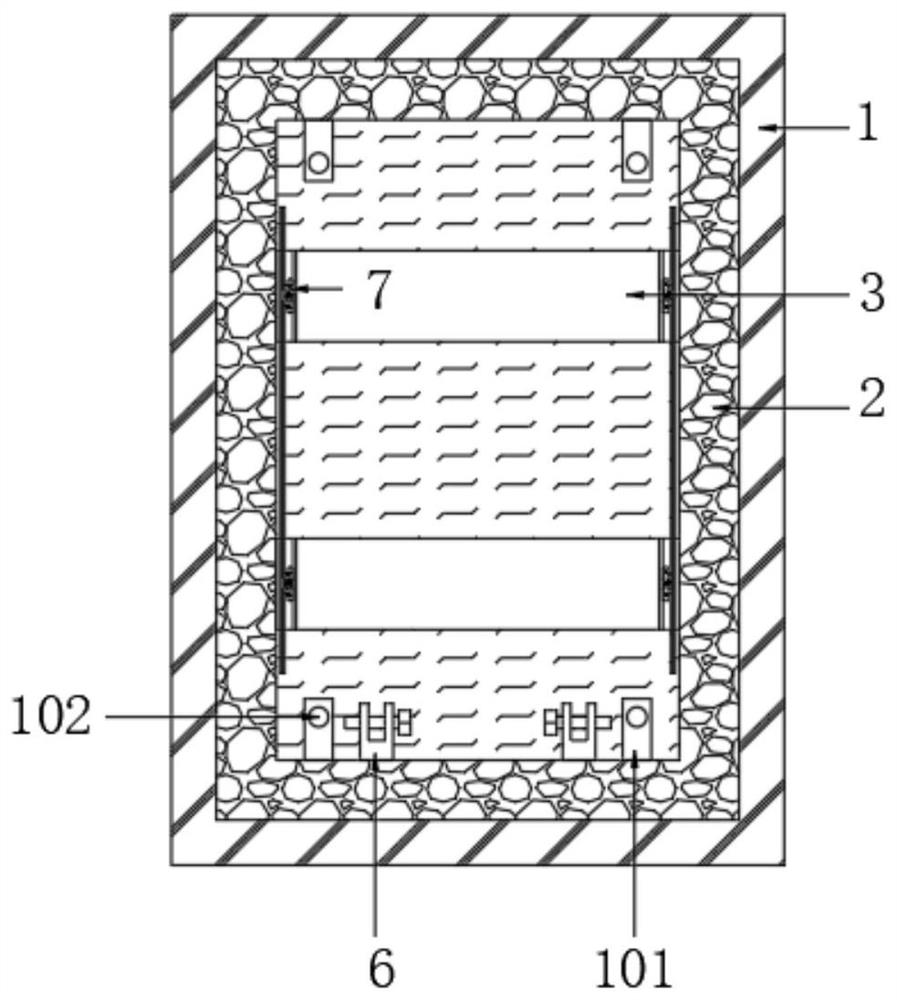
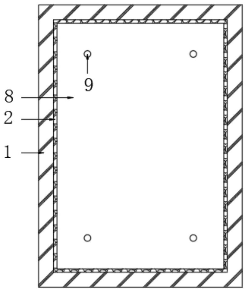
[0023] The present invention provides a technical solution: a splash-proof buried optical cable transfer box, please refer to Figure 1 to Figure 8 , including the outer pool 1, the inner wall of the outer pool 1 is provided with an inner pool 2, and the upper part of the inner wall of the inner pool 2 is horizontally provided with two sets of support plates 3 with the same structure, and the tops of the two sets of support plates 3 are in contact with the opti...


PUM


Abstract

The invention discloses a buried optical cable cross-connecting box capable of preventing water splashing and belongs to the technical field of optical cable cross-connecting boxes. Theburied optical cable cross-connecting box comprises an outer pool, wherein the inner wall of the outer pool is provided with an inner pool, the upper part of the inner wall of the inner pool is transversely provided with two groups of supporting plates with the same structure, and the tops of the two groups of supporting plates are in contact with an optical cable cross-connecting box body. Hanging brackets are arranged on the front side and the rear side of the top of the optical cable cross-connecting box body, the front end of the optical cable cross-connecting box body is rotationally connected with a rotating frame through a pin shaft, the front end of the rotating frame is fixedly connected to the inner wall of the inner pool, blocking mechanisms are attached to the two sides of the optical cable cross-connecting box body, and the top of the inner pool is covered with a cover plate. The movable block sequentially passes through the through hole and the water through hole to move upwards, so that foreign matters blocking the water through hole are ejected out, and the drainage difficulty of the cover plate can be reduced; therefore, the drainage of the cover plate can be ensured when the rainwater is too heavy and the water through hole is blocked by the foreign matters, and the optical cable cross-connecting box body cannot be splashed by the rainwater.

Description

technical field [0001] The invention relates to the technical field of optical cable transfer boxes, in particular to an underground buried optical cable transfer box that is waterproof and splash-proof. Background technique [0002] The buried optical cable transfer box is built in the existing communication pipeline manhole, so it can maximize the rational use of land resources and solve the problem of land shortage. The abundant groundwater in the manhole will speed up the transfer of heat and facilitate the cable transfer box. However, in actual use, part of the rainwater will flow into the manhole through the through hole of the manhole cover, and the other part will flow into the manhole through the gap between the bottom of the cover and the manhole. When it is blocked, most of the rainwater will flow out from the gap between the bottom of the cover plate and the manhole. At present, the two sides of the optical cable transfer box are relatively close to the inner wal...

Claims


Application Information

Patent Timeline
Patent Type & Authority Applications(China)
IPC IPC(8): G02B6/44
CPCG02B6/501
Inventor 贾平美
Owner 国网河南省电力公司卫辉市供电公司
Why Eureka
Try Eureka