
Transformer with multiple buffer mechanisms

A buffer mechanism and transformer technology, applied in transformer/inductor shell, transformer/reactor installation/support/suspension, transformer/inductor coil/winding/connection, etc., can solve the problem that the medium frequency transformer is difficult to adjust and the transformer is noisy , inconvenient to use and other problems, to achieve the effect of precise adjustment, reduce vibration and easy installation

Inactive Publication Date: 2021-06-04
GUIYANG BUREAU OF CHINA SOUTHERN POWER GRID CO LTD EHV TRANSMISSION CO
View PDF5 Cites 2 Cited by
  • Summary
  • Abstract
  • Description
  • Claims
  • Application Information

AI Technical Summary

Problems solved by technology

[0003] The existing adjustable intermediate frequency transformer is mainly composed of a metal shell, a magnetic core, an inductance coil and an adjustable magnetic cap. The inductance parameter can be adjusted by rotating the angle of the adjustable magnetic cap. The intermediate frequency transformer with this structure is not easy to adjust and is not easy to use. convenient
Moreover, large vibrations will be generated during the working process of the transformer. Most of the existing buffer structures use simple spring groups to realize the buffer function. The buffer effect is poor, and the noise of the transformer during operation is large, which has an impact on the surrounding environment.

Method used


Image

  • Transformer with multiple buffer mechanisms
  • Transformer with multiple buffer mechanisms
  • Transformer with multiple buffer mechanisms

Examples


Embodiment 1

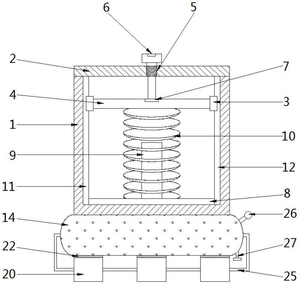
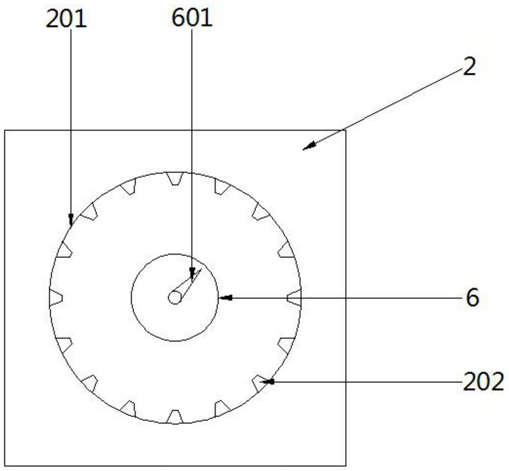
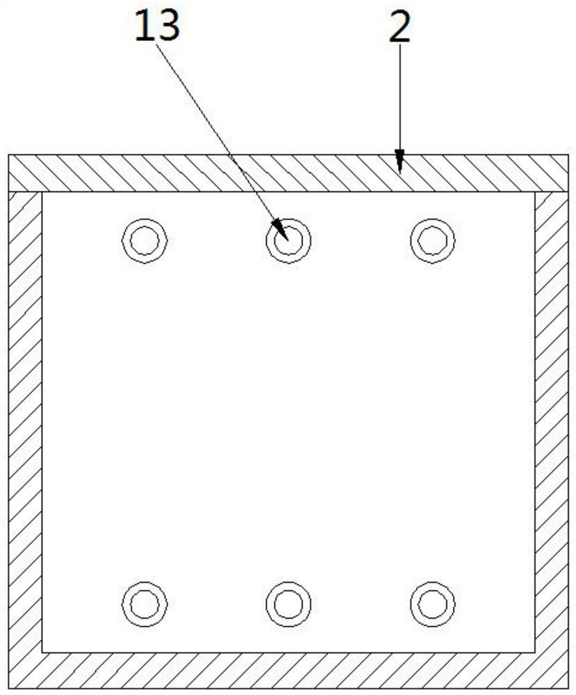
[0036] see Figure 1-2, a transformer with multiple buffer mechanisms, including an outer shell 1, the top of the outer shell 1 is provided with a top cover 2, the outer shell 1 is a cuboid outside and a hollow cylindrical structure inside, and the side wall of the outer shell 1 is provided with symmetrical The first slide rail 11 and the second slide rail 12 are set, and the first slide rail 11 and the second slide rail 12 are all slidably connected with a slider 3, and a connecting cross bar 4 is arranged between the sliders 3 on both sides, and the top The cover 2 is provided with a screw hole 5, the top of the top cover 2 is provided with an adjusting bolt 6, the bottom of the adjusting bolt 6 runs through the bottom of the screw hole 5, the top of the connecting cross bar 4 is provided with a positioning groove 7, and the adjusting bolt 6 passes through the positioning groove 7 Connected with the connecting bar 4, the bottom of the inner cavity of the outer casing 1 is pr...


PUM


Abstract

The invention discloses a transformer with multiple buffer mechanisms, and belongs to the technical field of power equipment. The transformer comprises an outer shell; a top cover is arranged at the top of the outer shell, and a first sliding rail and a second sliding rail which are symmetrically arranged are arranged on the side wall of the outer shell; a screw hole is formed in the top cover, an adjusting bolt is arranged at the top of the top cover, the bottom of the adjusting bolt penetrates through the bottom of the screw hole, a positioning groove is formed in the top of the connecting cross rod, and the adjusting bolt is connected with the connecting cross rod through the positioning groove; inductance parameters in the medium-frequency transformer can be changed through the adjusting knob, accurate adjustment of the inductance value of the transformer is achieved, use is convenient, controllability is high, wiring is convenient, vibration generated when the transformer works can be greatly reduced through the arranged multiple buffering mechanisms, and noise generated by vibration is reduced while noise is reduced.

Description

technical field [0001] The invention relates to the technical field of power equipment, more specifically, to a transformer with multiple buffer mechanisms. Background technique [0002] The transformer is a device that uses the principle of electromagnetic induction to change the AC voltage. The main components are the primary coil, the secondary coil and the iron core (magnetic core). The main functions are: voltage conversion, current conversion, impedance conversion, isolation, voltage stabilization (magnetic saturation transformer), etc. According to the use, it can be divided into: power transformers and special transformers (electric furnace transformers, rectifier transformers, power frequency test transformers, voltage regulators, mining transformers, audio transformers, intermediate frequency transformers, high frequency transformers, impact transformers, instrument transformers, electronic transformers , reactors, transformers, etc.). [0003] The existing adjus...

Claims


Application Information

Patent Timeline
Patent Type & Authority Applications(China)
IPC IPC(8): H01F27/02H01F27/06H01F27/29F16F15/023F16F15/067
CPCF16F15/023F16F15/067H01F27/02H01F27/06H01F27/29
Inventor 吕刚胡江王春唐华东张瑞亮罗宗源王伟谢辰昱刘华麟李道豫陈亮邱志远刘浩李毅易永亮蒋泽王恒汤勇
Owner GUIYANG BUREAU OF CHINA SOUTHERN POWER GRID CO LTD EHV TRANSMISSION CO
Learn More