
Low-voltage power distribution cabinet convenient to adjust

A power distribution cabinet, low-voltage technology, applied in the direction of electrical components, substation/switch layout details, etc., can solve the problems of cumbersome, many steps, wrong connection, etc., and achieve the effect of simplifying difficulty, avoiding overweight, and reducing the number of structures

Inactive Publication Date: 2021-06-04
安徽宇亚电气自动化有限公司
View PDF0 Cites 0 Cited by
  • Summary
  • Abstract
  • Description
  • Claims
  • Application Information

AI Technical Summary

Problems solved by technology

[0003] In the power distribution cabinet, the electrical equipment is usually installed on the rail, and the rail is usually fixed on the side wall of the power distribution cabinet with screws. When adjusting the position of the electrical equipment in the power distribution cabinet, it is easier to adjust the position horizontally. The vertical position adjustment is different. First, you need to remove the wires, remove the electrical equipment on the rail, and then use a screwdriver to remove the screws that fix the rail, and then weld a new rail fixing seat inside the power distribution cabinet, and then Install the rail back into the power distribution cabinet with a screwdriver and screws. After completing these operations, you need to connect the removed lines back. The steps required to adjust the position of the electrical equipment are not only many but also cumbersome, and there is still a need to connect the lines back. risk of wrong connection

Method used


Image

  • Low-voltage power distribution cabinet convenient to adjust
  • Low-voltage power distribution cabinet convenient to adjust
  • Low-voltage power distribution cabinet convenient to adjust

Examples


Embodiment Construction

[0042] The following will clearly and completely describe the technical solutions in the embodiments of the present invention with reference to the accompanying drawings in the embodiments of the present invention. Obviously, the described embodiments are only some, not all, embodiments of the present invention. Based on the embodiments of the present invention, all other embodiments obtained by persons of ordinary skill in the art without making creative efforts belong to the protection scope of the present invention.

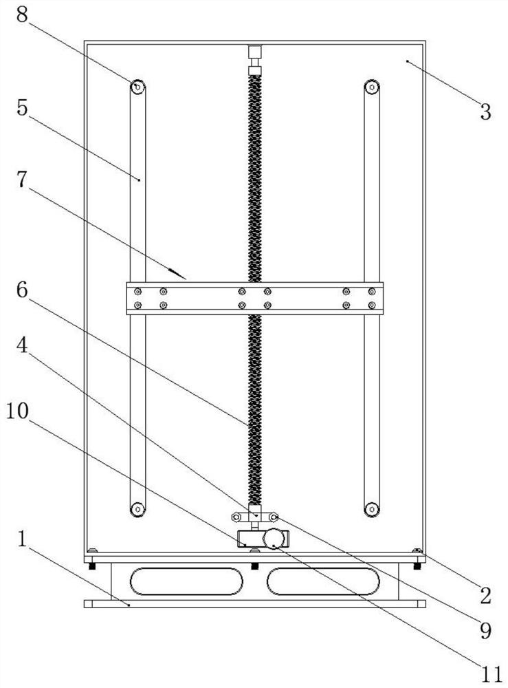
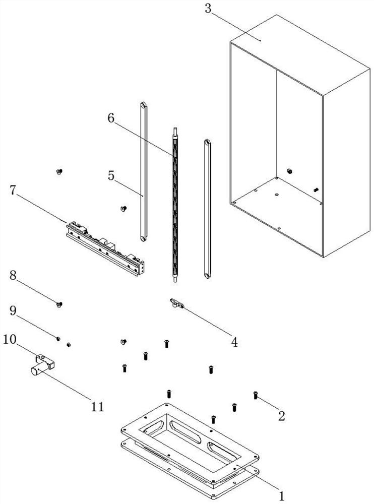
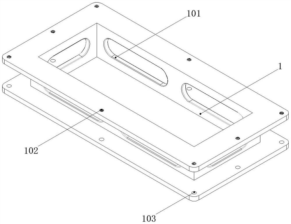
[0043] The present invention provides such Figure 1-22 A low-voltage power distribution cabinet that is easy to adjust is shown, including a base 1, a cabinet body 3, a bracket 4, a slide rail 5, a threaded rod 6, an electrical mounting component 7, a reducer 10, and a motor 11. The base 1 Located below the cabinet body 3, the base 1 is an integral frame-like structure made by casting. There are several seat weight-reducing grooves 101 for shock absorption in...


PUM


Abstract

A low-voltage power distribution cabinet convenient to adjust disclosed by the present invention comprises a base, a cabinet body, a bracket, a slide rail, a threaded rod, an electric appliance mounting assembly, a speed reducer and a motor, the base is located below the cabinet body, the base is of an integrated frame-shaped structure manufactured by casting, a plurality of base weight reduction grooves for damping are formed in the middle of the base, a base threaded hole is formed in a plate-shaped part on the upper side of the base, a base through hole is formed in the plate-shaped part on the lower side of the base, a base connecting screw is arranged in the base threaded hole, the upper side part of the base connecting screw is located in a cabinet connecting hole in the cabinet body, the outline of the cabinet body is of a rectangular box-shaped structure, a plurality of cabinet connecting holes distributed in a rectangular array are arranged on the bottom surface of the cabinet body, and two cabinet wire holes are arranged on the bottom surface of the cabinet body. According to the low-voltage power distribution cabinet convenient to adjust, the position of each electric appliance mounting assembly can be adjusted as required, manual operation is not needed in the adjusting process, and the low-voltage power distribution cabinet is suitable for being widely popularized and used.

Description

technical field [0001] The invention belongs to the technical field of power distribution cabinets, and in particular relates to a low-voltage power distribution cabinet that is easy to adjust. Background technique [0002] Power distribution cabinets are divided into power distribution cabinets, lighting distribution cabinets, and metering cabinets, and are the final equipment of the power distribution system. The power distribution cabinet is a general term for the motor control center. The power distribution cabinet is used in the occasions where the load is relatively scattered and there are few circuits; the motor control center is used in the occasions where the load is concentrated and there are many circuits. They distribute the electric energy of a certain circuit of the upper-level power distribution equipment to the nearest load. This level of equipment shall provide protection, monitoring and control of the load. [0003] In the power distribution cabinet, the...

Claims


Application Information

Patent Timeline
Patent Type & Authority Applications(China)
IPC IPC(8): H02B1/32
CPCH02B1/32
Inventor 缪同悦沈丽丽
Owner 安徽宇亚电气自动化有限公司
Learn More