Hemostasis rescue device for cardiology department
A technology of cardiology and installation mechanism, which is applied in the field of hemostasis and rescue devices in cardiology, which can solve the problems of time-consuming and labor-consuming, inconvenient adjustment, complex structure, etc., and achieve the effect of improving practicability and increasing practicability
- Summary
- Abstract
- Description
- Claims
- Application Information
AI Technical Summary
Problems solved by technology
Method used
Image
Examples
Embodiment 1
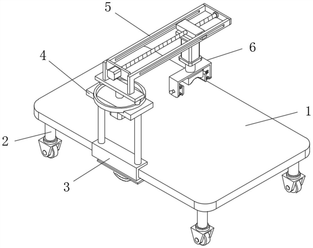
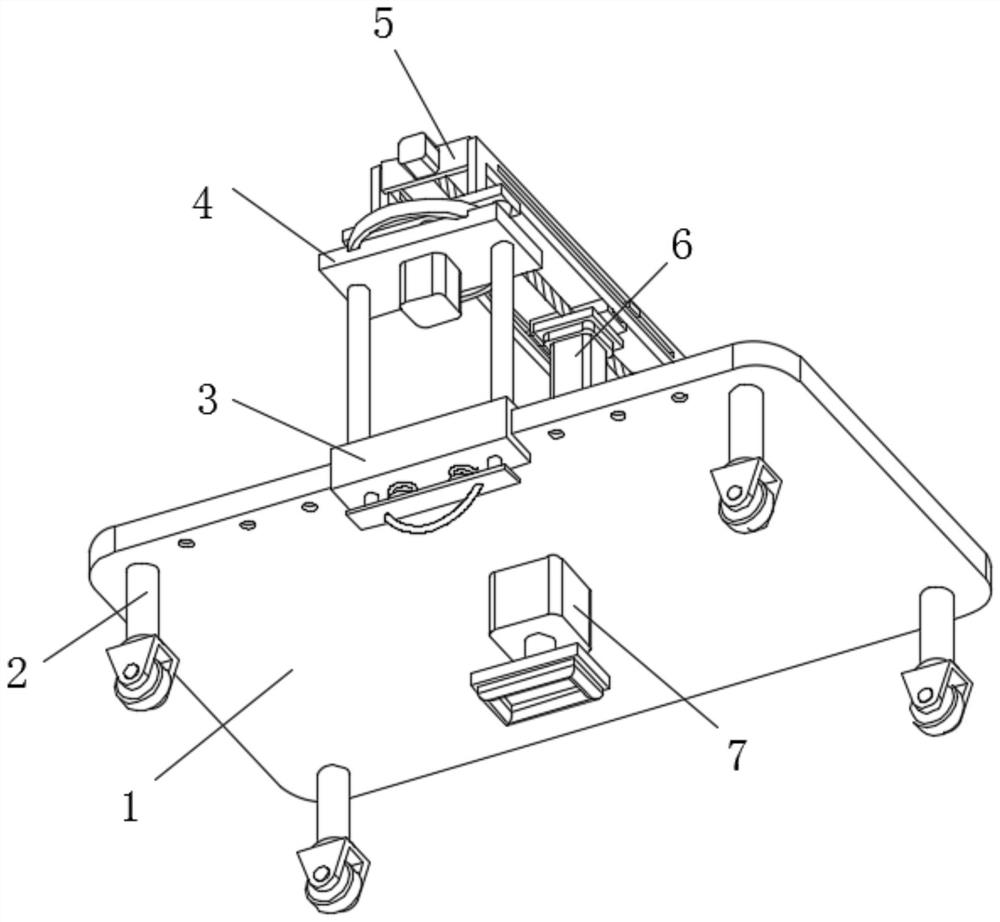
[0050] Such as Figure 1-2 As shown, a hemostatic rescue device for cardiology according to an embodiment of the present invention includes a table top 1, a moving assembly 2, an installation mechanism 3, a rotating mechanism 4, a moving mechanism 5, a hemostasis mechanism 6, and a stabilizing assembly 7;
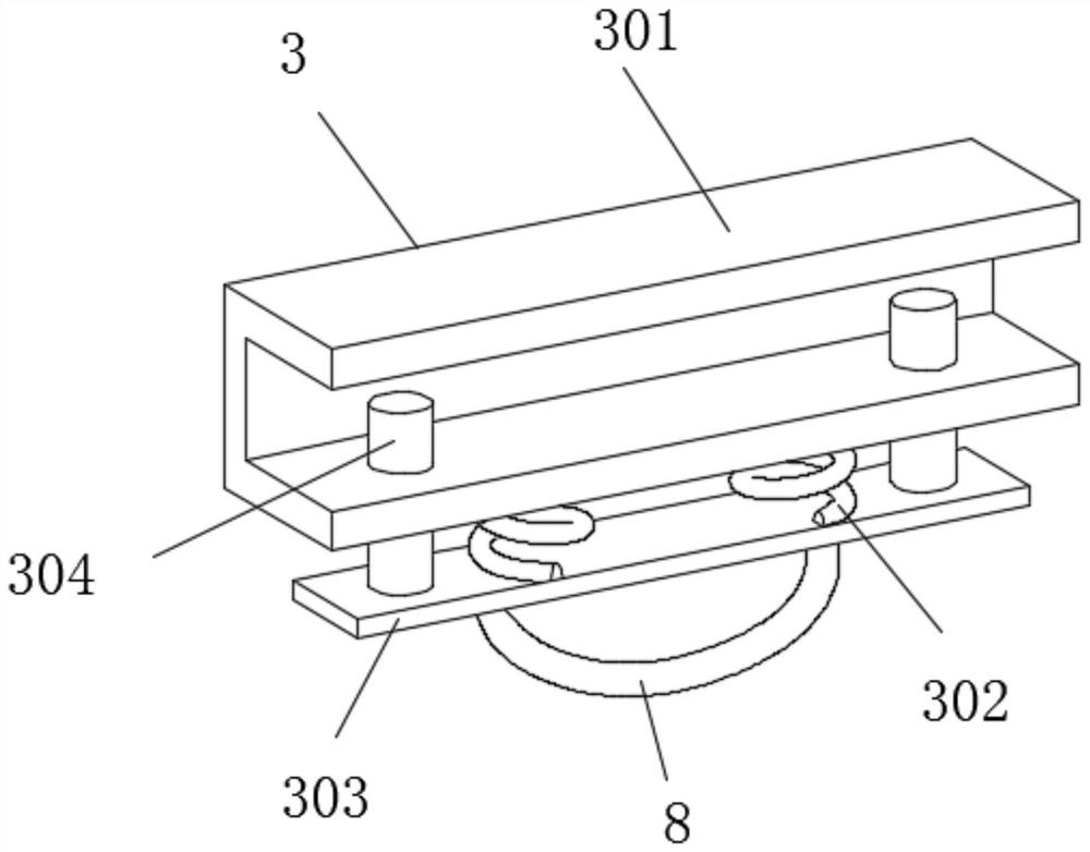
[0051] Among them, such as Figure 1-2 As shown in and 3, the installation mechanism 3 includes a card frame 301, two installation springs 302, a connecting plate 303 and two card bars 304, the card frame 301 is clamped at the edge of the table 1, and the two The mounting springs 302 are symmetrically installed on the bottom of the card frame 301, the top of the connecting plate 303 is fixedly connected to the bottoms of the two mounting springs 302, and the two clamping rods 304 are respectively fixedly connected to the connecting plate Both sides above 303;
[0052] Among them, such as Figure 1-2 and Figure 4 As shown, the rotating mechanism 4 includes two supporting ...
Embodiment 2
[0057] Such as Figure 1-2 and Figure 7 As shown, the difference between this embodiment and Embodiment 1 is that the moving assembly 2 includes a leg 201 and a moving wheel 202, the leg 201 is fixedly installed on the bottom of the table 1, and the leg 201 The bottom and the moving wheel 202 are flexibly connected by a cardan shaft 203 .
[0058] By adopting the above-mentioned technical scheme, it is convenient to move the device in multiple directions, so it is convenient for the medical staff to move and operate the device.
Embodiment 3
[0060] Such as Figure 1-2 and Figure 8 As shown, the difference between this embodiment and Embodiment 2 is that the stabilizing component 7 includes an electric push rod 701 and a stabilizing block 702, the electric push rod 701 is fixedly installed on the bottom of the table 1, and the stabilizing The block 702 is fixedly installed on the output end of the electric push rod 701 .
[0061] By adopting the above technical solution, after the device is moved, the electric push rod 701 can drive the stabilizing block 702 to move down and touch the ground, thereby increasing the stability of the device after being moved.
PUM
 Abstract
Description
Claims
Application Information
 - R&D
- Intellectual Property
- Life Sciences
- Materials
- Tech Scout
- Unparalleled Data Quality
- Higher Quality Content
- 60% Fewer Hallucinations
Browse by: Latest US Patents, China's latest patents, Technical Efficacy Thesaurus, Application Domain, Technology Topic, Popular Technical Reports.
© 2025 PatSnap. All rights reserved.Legal|Privacy policy|Modern Slavery Act Transparency Statement|Sitemap|About US| Contact US: help@patsnap.com


