Automatic aligning and clamping device and method for circular parts

A ring type, parts technology, applied in the direction of positioning device, metal processing machinery parts, clamping, etc.

Active Publication Date: 2021-06-08
宜昌长机科技有限责任公司
View PDF7 Cites 8 Cited by
  • Summary
  • Abstract
  • Description
  • Claims
  • Application Information

AI Technical Summary

Problems solved by technology

[0007] In order to solve the above technical problems, the present invention provides an automatic aligning and clamping device and method for ring-shaped parts, which solves the problem of aligning and clamping large-sized ring-shaped parts, and the adjustment is very convenient

Method used


Image

  • Automatic aligning and clamping device and method for circular parts
  • Automatic aligning and clamping device and method for circular parts
  • Automatic aligning and clamping device and method for circular parts

Examples


Embodiment 1

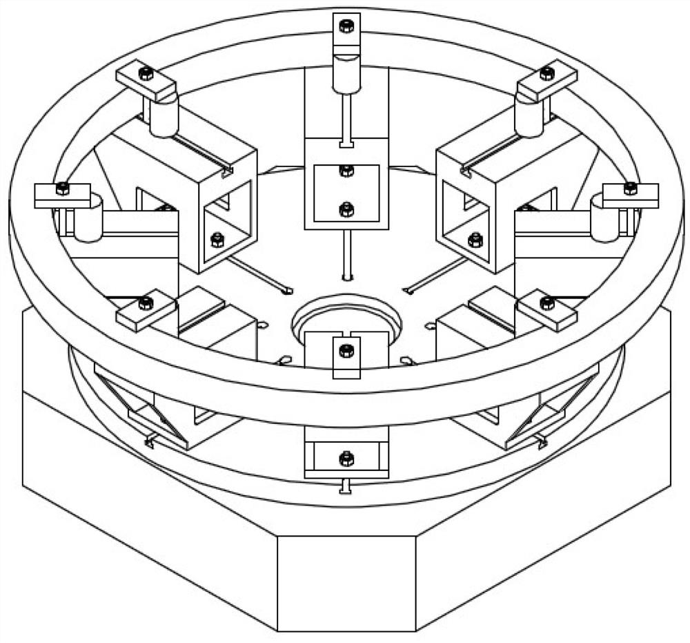
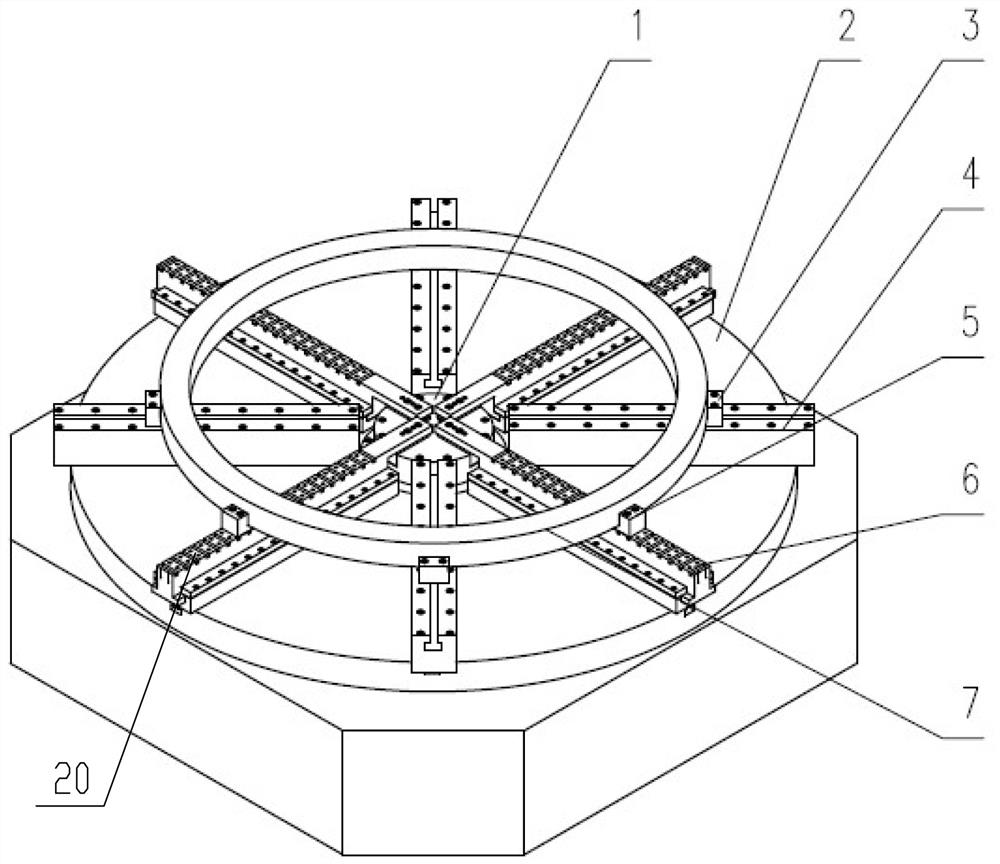
[0036] See Figure 2-4 A ring-type part automatically finds a clipper, which includes a rotary table 2, and the central portion of the rotary table 2 is fixedly mounted with a power chuck 1; the rotary table 2, and is located in the power chuck 1 The peripheral fabric processing has a plurality of T-slots 18 that are radially arranged, and a rail assembly 19 is fixed to the T-slot 18, and the rail assembly 19 is mounted with a slide 6, The inner end of the slide rail 6 is fixedly connected to the jaw 17 of the power chuck 1, and the slide rail 6 is synchronized under shrinkage or deployment operation of the plurality of jaws 17; top setting of the rail 6 There is a limit structure for limiting the workpiece. By using the above-described structure, the power chuck 1 of the appropriate size series is selected according to the diameter of the workpiece, and the power chuck 1 is applied, and the clamping operation of the power chuck 1 is used to realize the automatic workpiece 7. Care ...

Embodiment 2

[0044] The method of finding a piercing clip is used to automatically find a plurality of ring parts, including the following steps:

[0045] Step 1: Regulate the assembly position on the claw 17 on the jaw 17 according to the outer dimensions of the workpiece 7;

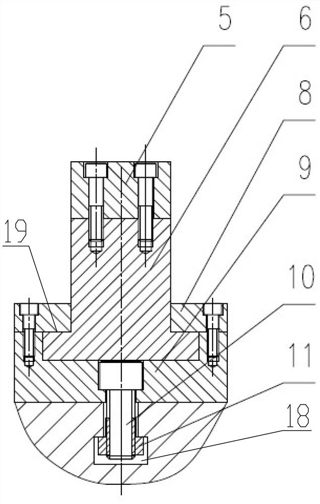
[0046] Step 2: After the positional adjustment of the transfer pad 14 is completed, the rail 6 is fixed to the correct position on the transition pad 14 by the cylindrical pin 13;

[0047] Step 3: Tighten the rail 6 to the jaw 17 by screw 12;

[0048] Step 4: The casing 5 is disposed at a suitable card slot 20 on the rail 6 according to the different diameter sizes of the workpiece 7;

[0049] Step 5: Start the power chuck 1, shrink by the drive jaw 17 synchronized by the power chuck 1, and then drive the slide rail 6 through the jaws 17, through the slide rail 6, and then by multiple synchronous motionsThe seat 5 clamps the workpiece 7 and ensures that the center of the workpiece is coincident with the center of the pow...


PUM


Abstract

The invention provides an automatic aligning and clamping device and method for annular parts. The automatic aligning and clamping device comprises a rotating table, and a power chuck is fixedly mounted in the center of the rotating table; a plurality of T-shaped grooves arranged in the radial direction are evenly formed in the rotating table and located on the periphery of the power chuck, sliding rail assemblies are fixed to the T-shaped grooves, sliding rails are mounted on the sliding rail assemblies in a sliding fit mode, the inner side ends of the sliding rails are fixedly connected with clamping jaws of the power chuck through fine adjustment mechanisms, and the sliding rails are synchronously driven under the contraction or expansion action of the multiple clamping jaws; and a limiting structure used for limiting a workpiece is arranged at the tops of the sliding rails. The problems of alignment and clamping of large-size annular parts are solved, and adjustment is very convenient.

Description

Technical field [0001] The present invention belongs to the field of ring-type workpiece mount tool, in particular to a circular ring part automatically finds a clipper and method, in particular, an annular part of the annular part of the diameter of the part, and the automatic finding of the annular part of the circular part of the parts. Background technique [0002] See figure 1 The existing large ring parts mechanical processing existing mounting scheme is usually based on the size of the workpiece, and the corresponding number of parts support seats are arranged at the appropriate position of the machine tool worksheet, and the parts support holder is fixed to the machine tool tool by the T-bolt. On, then the workpiece that needs to be processed is artificially found to be fixed by the pressure plate on the support. This program can meet the mechanical processing of a ring-type part of different sizes of size by adjusting the position of the parts of the machine toolhouse, b...

Claims


Application Information

Patent Timeline
Patent Type & Authority Applications(China)
IPC IPC(8): B23Q3/06B23Q3/18
CPCB23Q3/062B23Q3/18
Inventor 王维
Owner 宜昌长机科技有限责任公司
Why Eureka
Try Eureka