Metal heat treatment subsequent annealing device

A metal heat treatment and annealing device technology, applied in heat treatment furnaces, heat treatment equipment, furnaces, etc., can solve the problems of inconvenient access to metal bars and affect work efficiency, and achieve the effects of novel design, improved work efficiency, and convenient manual operation.

Pending Publication Date: 2021-06-08
厦门澄志精密科技有限公司
View PDF5 Cites 1 Cited by
  • Summary
  • Abstract
  • Description
  • Claims
  • Application Information

AI Technical Summary

Problems solved by technology

[0003] The purpose of the present invention is to solve the disadvantages of inconveniently taking the annealing treatment of metal rods in the prior art and affecting the working efficiency, and propose a subsequent annealing device for metal heat treatment

Method used


Image

  • Metal heat treatment subsequent annealing device
  • Metal heat treatment subsequent annealing device
  • Metal heat treatment subsequent annealing device

Examples


Embodiment Construction

[0017] The following will clearly and completely describe the technical solutions in the embodiments of the present invention with reference to the accompanying drawings in the embodiments of the present invention. Obviously, the described embodiments are only some, not all, embodiments of the present invention.

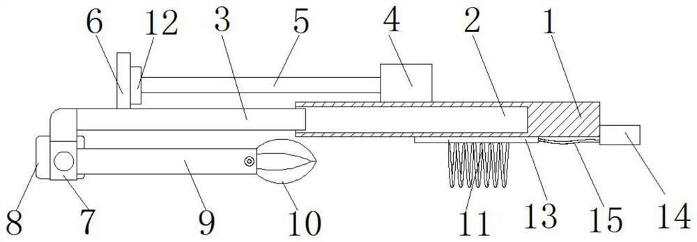
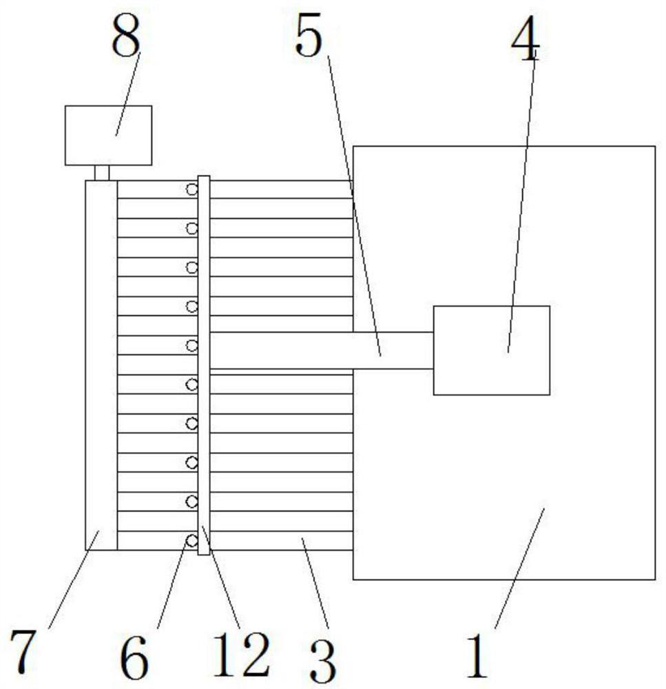
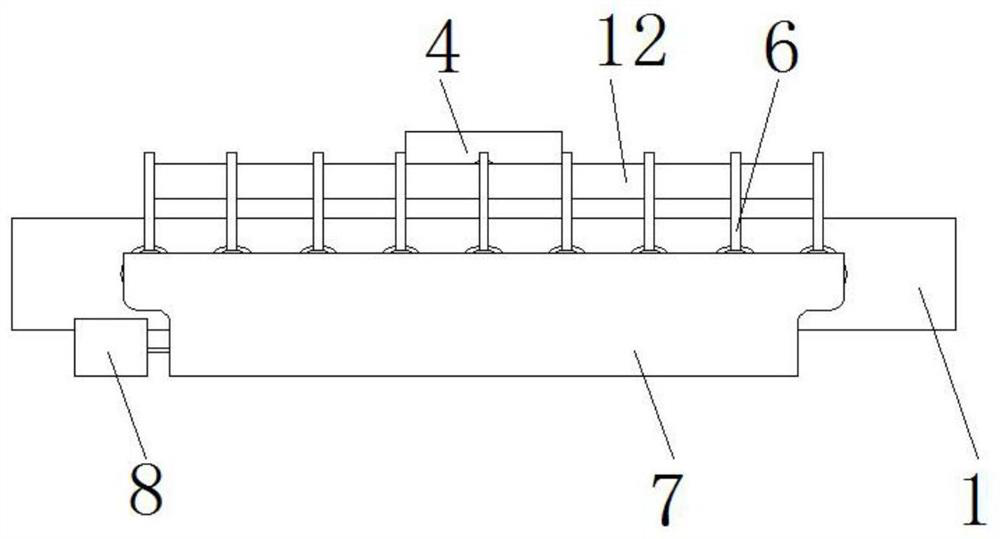
[0018] In this example, refer to Figure 1-3 , a metal heat treatment follow-up annealing device, comprising a box body 1, a plurality of identical slideways 2 are provided inside the box body 1, the slideways 2 are arranged in parallel, the slideway 2 runs through the inner wall of one side of the box body 1, and the slideways 2 A slidable slide bar 3 is arranged inside, a push rod motor 4 is arranged on the top of the box body 1, and a horizontal push arm 5 is arranged at the output end of the push rod motor 4, and the end of the push arm 5 far away from the push rod motor 4 is docked on the slide On the straight rod 6 provided on the top of the bar 3, the end of t...


PUM


Abstract

The invention relates to the technical field of metal heat treatment, and particularly relates to a metal heat treatment subsequent annealing device. The metal heat treatment subsequent annealing device comprises a box body, wherein a plurality of identical slide ways are formed in the box body; the slide ways penetrate through the inner wall of one side of the box body; a slidable sliding rod is arranged in the slide ways; a push rod motor is arranged at the top of the box body; one end, far away from the push rod motor, of a push arm arranged at the output end of the push rod motor is in butt joint with a straight rod arranged at the top of the sliding rod; a mounting base is arranged at the end part, far away from the box body, of the sliding rod; a rotatable movable arm is arranged at the bottom of the mounting base; an electric clamping jaw is arranged at the end part, far away from the mounting base, of the movable arm; the electric clamping jaw is used for clamping a metal rod; and a spiral electric heating wire is arranged at the bottom of the box body. According to the metal heat treatment subsequent annealing device, the problem that the working efficiency is influenced due to the fact that the metal rod is inconvenient to take during annealing treatment is solved, the annealing device is provided, so that a worker can conveniently and rapidly take the metal rod and execute annealing treatment, and the device is simple and efficient.

Description

technical field [0001] The invention relates to the technical field of metal heat treatment, in particular to a subsequent annealing device for metal heat treatment. Background technique [0002] Annealing is a metal heat treatment process, which refers to heating the metal to a certain temperature, keeping it for a sufficient time, and then cooling it at an appropriate speed. Metal bars often need to be annealed after heat treatment. The traditional bar has the following disadvantages in the annealing process. Due to the heating of the bar, its surface temperature is very high, and it is inconvenient to take and replace it manually, which will waste a lot of time and work. low efficiency. Contents of the invention [0003] The object of the present invention is to solve the disadvantages in the prior art that it is inconvenient to take the annealing treatment of metal rods and affect the working efficiency, and proposes a subsequent annealing device for metal heat treatm...

Claims


Application Information

Patent Timeline
IPC IPC(8): C21D9/00C21D1/26
CPCC21D9/0075C21D1/26
Inventor 陈昊
Owner 厦门澄志精密科技有限公司
Why Eureka
Try Eureka