Geological drill rod

A geological drill and rod body technology, applied in the direction of drill pipe, drill pipe, drilling equipment, etc., can solve the problems of poor torsional performance, corrosion, impracticality, etc., to improve impact resistance, improve torsional performance, improve The effect of service life

Pending Publication Date: 2021-06-08
山东源运通矿山装备科技有限公司
View PDF6 Cites 0 Cited by
  • Summary
  • Abstract
  • Description
  • Claims
  • Application Information

AI Technical Summary

Problems solved by technology

[0003] Basically, most of the drill pipes are connected by simple threads, because the complicated connection methods are not suitable for the needs of actual production operations and are not practical.
However, the threaded connection method often causes corrosion due to corrosion and other conditions, resulting in poor torsion resistance, which in turn leads to the failure of the drill pipe to be used normally.

Method used


Image

  • Geological drill rod
  • Geological drill rod
  • Geological drill rod

Examples


no. 1 example

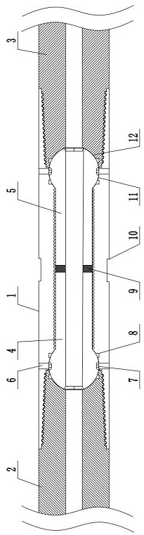
[0023] First embodiment (see figure 1 ):

[0024] Geological drilling rods, including a connecting pipe 1, a left spherical connecting rod 4 and a right spherical connecting rod 5; the left and right ends of the connecting pipe 1 are respectively provided with a left rod body 2 and a right rod body 3; the two ends of the connecting pipe 1 A connecting pipe concave groove 11 is provided; the connecting ends of the left rod body 2 and the right rod body 3 and the connecting pipe 1 are provided with a connecting rod concave groove 12; the outer ends of the left ball connecting rod 4 and the right ball connecting rod 5 It is an arc-shaped structure; the arc-shaped structure is embedded in the arc-shaped groove formed by connecting the connecting pipe concave groove 11 and the connecting rod concave surface groove 12 and fits together; the left ball joint connecting rod 4 and the right ball joint connecting rod The inner end of 5 is embedded in the connecting pipe 1; the arc struc...

Embodiment 2

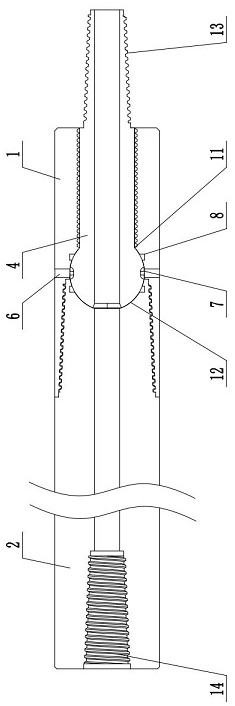
[0035] The difference between Embodiment 2 and Embodiment 1 is that a single ball-joint connecting rod is adopted, specifically, one end of the left ball-joint connecting rod 4 is a spherical arc-shaped structure, and the other end is provided with a connecting external thread 13 . At the same time, the left end of the left rod body 2 is provided with a connecting internal thread 14 matching the connecting external thread 13 .

Embodiment 3

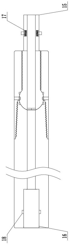
[0037] The difference between embodiment 3 and embodiment 2 is that the connecting external thread 13 is replaced by a polygonal prism pin 15 ; meanwhile, the left end of the left rod body 2 is provided with a groove 16 matching the polygonal prism pin 15 . At the same time, the polygonal prism plug 15 is provided with a card bean 17; the groove 16 is provided with a card slot 18 matching the card bean 17.


PUM


Abstract

The invention discloses a geological drill rod. The geological drill rod comprises a connecting pipe, a left ball head connecting rod and a right ball head connecting rod. A left rod body and a right rod body are correspondingly arranged at the left end and the right end of the connecting pipe; connecting pipe concave grooves are formed in the two ends of the connecting pipe; connecting rod concave grooves are formed in the ends, connected with the connecting pipe, of the left rod body and the right rod body; the outer ends of the left ball head connecting rod and the right ball head connecting rod are of arc-shaped structures; the arc-shaped structures are embedded in an arc-shaped groove formed by connecting the concave groove of the connecting pipe and the concave groove of the connecting rod and is attached to the arc-shaped groove; the inner ends of the left ball head connecting rod and the right ball head connecting rod are embedded in the connecting pipe; limiting holes are formed in the arc-shaped structures; insertion grooves are formed in the position, corresponding to the limiting holes, of the connecting pipe; and pins are arranged between the slots and the limiting holes. Compared with the prior art, the geological drill rod has the beneficial effects that the structure is simple, connection is convenient and fast, the connecting position of the drill rod is prevented from being eroded through optimization design, and the service life of the drill rod is prolonged.

Description

technical field [0001] The invention relates to the field of drill pipes, in particular to a geological drill pipe. Background technique [0002] The drill pipe plays the role of transmitting power and conveying mud in the drill string system. During the working process, it will be subjected to extremely harsh alternating torque and vibration. Therefore, it must have good torsion resistance and impact resistance to ensure the normal use of the drill pipe. . [0003] Basically, most of the drill pipes are connected by simple threads, because the complicated connection methods are not suitable for the needs of actual production operations and are not practical. However, the way of threaded connection often causes corrosion due to corrosion and other conditions, resulting in poor torsional performance, which in turn makes the drill pipe unable to be used normally. Contents of the invention [0004] The invention provides a geological drill pipe, which is characterized by si...

Claims


Application Information

Patent Timeline
Patent Type & Authority Applications(China)
IPC IPC(8): E21B17/05E21B17/042E21B17/00
CPCE21B17/05E21B17/0426E21B17/00
Inventor 张凯彭龙黄庆涛高超侯新领袁吉瑞
Owner 山东源运通矿山装备科技有限公司
Why Eureka
Try Eureka