
Triangular rotor pump

A triangular rotor and rotor body technology, applied in the direction of rotary piston pumps, pumps, pump components, etc., can solve the problems that gaps cannot be completely eliminated, processing and assembly technology, and high cost requirements

Pending Publication Date: 2021-06-08
POSITEC POWER TOOLS (SUZHOU) CO LTD
View PDF0 Cites 0 Cited by
  • Summary
  • Abstract
  • Description
  • Claims
  • Application Information

AI Technical Summary

Problems solved by technology

At present, according to the different working pressure of the triangular rotor pump, the existing technology usually adopts three sealing schemes. When the pressure requirement is not high, the radial top of the triangular rotor is sealed with a sealing plate and a spring, and the end faces of both sides of the triangular rotor are sealed with gaps. ;When the pressure requirement is high, the radial top of the triangular rotor is sealed with a sealing plate and a spring, and the end faces of both sides of the triangular rotor are sealed with a sealing strip and a spring; if the pressure requirement is higher, except for the radial top of the triangular rotor. The sealing sheet and the spring cooperate to seal. In addition to sealing the two sides of the triangular rotor with sealing strips and springs, it is necessary to install sealing pins at both ends of the sealing sheet at the radial top of the triangular rotor to further prevent liquid from leaking from the sealing sheet and the sealing sheet. The gap between the sealing pins leaks, but these three sealing schemes cannot completely eliminate the gap due to structural problems. At the same time, the above-mentioned scheme of sealing with springs involves many structural parts, and the subsequent processing and assembly process and cost requirements are very high.

Method used


Image

  • Triangular rotor pump
  • Triangular rotor pump
  • Triangular rotor pump

Examples


Embodiment Construction

[0049] In order to make the purpose, technical solutions and advantages of the embodiments of the present invention more clear, the technical solutions in the embodiments of the present invention will be clearly and completely described below in conjunction with the drawings in the embodiments of the present invention.

[0050] The technical solutions provided by the embodiments of the present invention are described below with reference to the accompanying drawings.

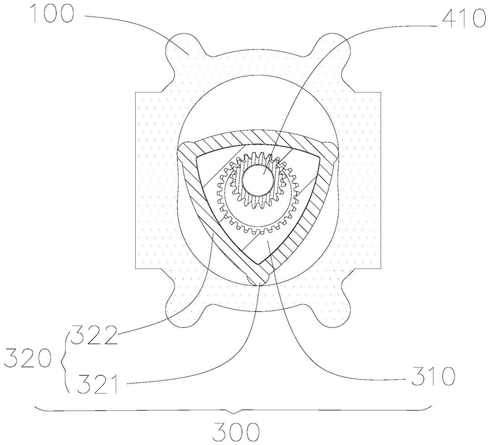
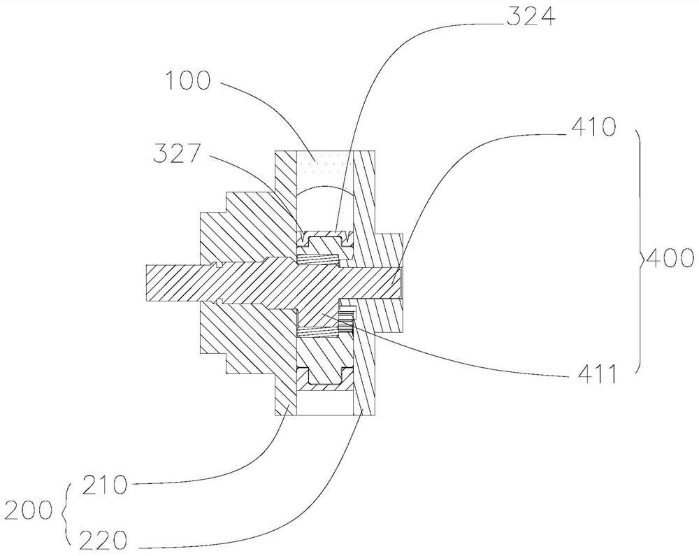
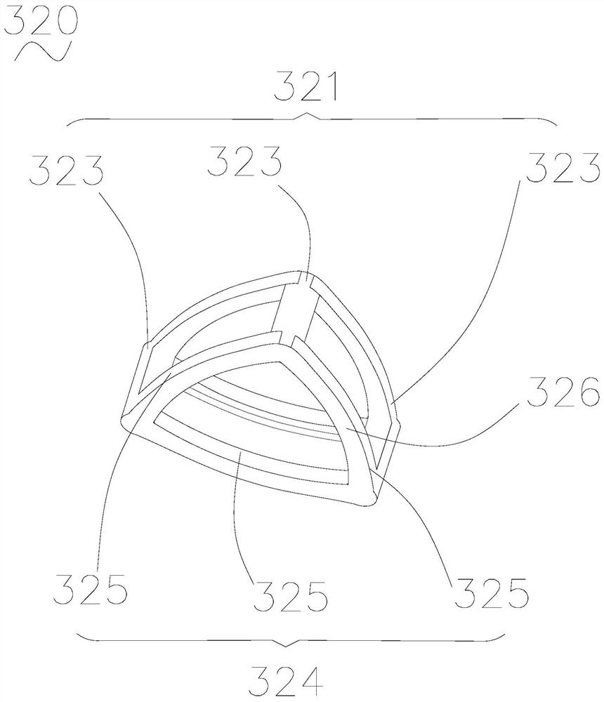
[0051] like figure 1 , figure 2 , image 3 , Figure 4 as well as Figure 5 As shown, the present invention provides a triangular rotor pump, the triangular rotor pump is used for the delivery of fluid in the washing machine, including a housing, and the housing has a side wall 100 and an end cover 200 connected to the side wall 100, wherein, The end cover 200 includes a first end cover 210 and a second end cover 220, and the first end cover 210 and the second end cover 220 are fixed on both ends of the sid...


PUM


Abstract

The invention relates to a triangular rotor pump which comprises a shell. The shell comprises a side wall, a first end cover and a second end cover, the first end cover and the second end cover are arranged at the two ends of the side wall respectively, the triangular rotor pump further comprises a triangular rotor arranged in the shell and an eccentric assembly for driving the triangular rotor, and the triangular rotor comprises a rotor body and a sealing piece arranged on the rotor body; the sealing piece is an elastic structural piece, and the rotor body comprises three top ends and side faces facing the first end cover and the second end cover respectively, wherein the sealing piece comprises three first sealing parts arranged at the three top ends respectively, and each first sealing part abuts against the inner surface of the side wall to form a radial sealing face blocking adjacent working cavities; the sealing piece further comprises two second sealing parts, the two second sealing parts are arranged at the two ends of the rotor body in the axial direction respectively, and the second sealing parts abut against the first end cover and the second end cover respectively to form end face sealing faces; and the two ends of the first sealing parts are in gapless fit with the two second sealing parts correspondingly, and radial sealing and end face sealing are achieved.

Description

technical field [0001] The invention relates to the technical field of rotor pumps, in particular to a triangular rotor pump. Background technique [0002] In the field of rotor pump technology, the internal working chamber of the triangular rotor pump is divided into three closed spaces by the triangular rotor. With the help of the periodic changes of the three closed volume spaces during the movement of the triangular rotor, fluid delivery is realized, while the triangular rotor pump The prerequisite for the realization of the function is that the volume of the pump body can always ensure sufficient sealing. Therefore, the sealing has become an important indicator for testing the performance of the triangular rotor pump. [0003] In order to improve the sealing performance of the triangular rotor pump, the three top ends and the end faces on both sides of the triangular rotor need to be sealed by contact with the inner wall of the pump body, including reliable sealing at t...

Claims


Application Information

Patent Timeline
Patent Type & Authority Applications(China)
IPC IPC(8): F04C2/22F04C15/00
CPCF04C2/22F04C15/00F04C15/0015F04C2240/20F05C2225/00F05C2225/02
Inventor 赵凤丽查霞红李敏行
Owner POSITEC POWER TOOLS (SUZHOU) CO LTD
Learn More