
A shaft distribution proportional servo valve

A proportional servo valve, shaft distribution technology, applied in servo motor components, valve devices, multi-port valves, etc., can solve problems affecting output power characteristics, affecting heat dissipation characteristics, actuator failures, etc., to reduce driving torque and reduce shafts. Quality, the effect of increasing the flow capacity

Active Publication Date: 2022-02-18
TONGJI UNIV
View PDF0 Cites 0 Cited by
  • Summary
  • Abstract
  • Description
  • Claims
  • Application Information

AI Technical Summary

Problems solved by technology

[0003] Its power supply is mainly driven by PWM signal. The movement of the spool in the valve body is mainly supported by the hydraulic oil film. After the oil pollution particles flow into the gap between the spool and the valve body, it will affect the smoothness of the movement of the spool. If the proportional coil is in the energized state for a long time , the spool is easy to get stuck, causing failure of the actuator, and due to the limited installation space, the size of the proportional coil will limit its maximum holding force and affect its output power characteristics. The fluid flows through the cavity formed by the spool / valve body body, the generated hydrodynamic force also limits the flow capacity; in addition, the size of the proportional coil also affects the heat dissipation characteristics. It is easy to burn the coil in a high temperature or high humidity environment, and the plastic packaging process of the coil and the way of electrical connection will also affect the Affect the waterproof level

Method used


Image

  • A shaft distribution proportional servo valve
  • A shaft distribution proportional servo valve
  • A shaft distribution proportional servo valve

Examples


Embodiment

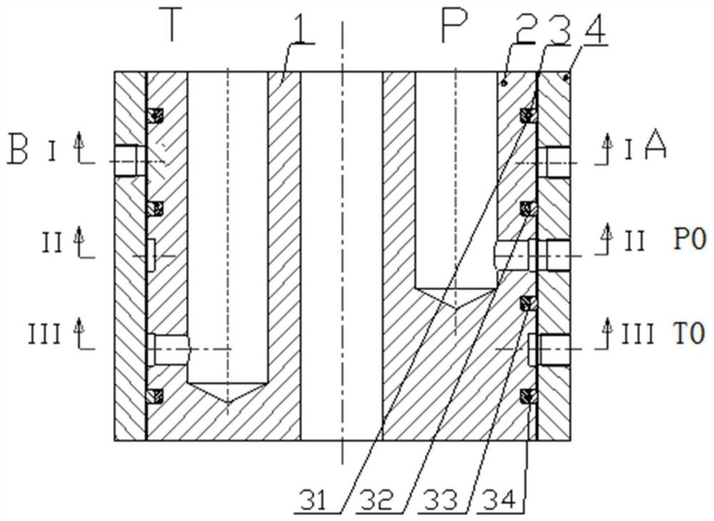
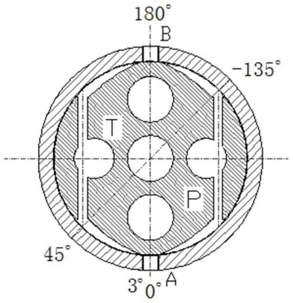
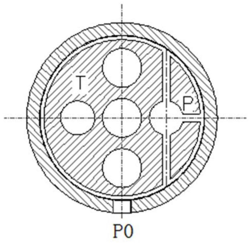
[0040] Such as Figure 1-4 As shown, the present invention provides an axial flow distribution proportional servo valve, which includes an internal axial flow distribution valve core rotor 2, an external axial flow distribution valve body stator 4 and multiple sets of sealing rings; by adjusting the axial flow distribution valve core rotor 2 to rotate to different angles , the continuous proportional communication between the working oil port and the oil supply port P0, and the oil return port T0 realizes the continuous different proportional speed control of the actuator action, and the actuator can maintain the same state within a specific rotation angle range, with parts Less, convenient processing, compact structure, simple, convenient adjustment, large flow capacity, easy maintenance, high repeatability, etc.

[0041] The rotor 2 of the axial distribution valve core and the stator 4 of the axial distribution valve body pass through four sealing rings 3 from top to bottom ...


PUM


Abstract

The invention relates to an axial distribution proportional servo valve, which comprises an axial distribution valve body stator and an axial distribution valve core rotor rotatably installed in the inner cavity of the axial distribution valve body stator, the axial distribution valve body stator and the axial distribution valve core The rotor is provided with three sealing areas in sequence from top to bottom, and the side wall of the stator of the shaft distribution valve body is provided with working oil ports, oil supply ports and oil return ports corresponding to the three sealing areas in sequence from top to bottom. The working oil port is respectively connected with the external actuator, and the oil supply port and the oil return port are respectively connected with the external oil source. The shaft distribution valve core rotor is provided with an oil supply channel, an oil return channel and a through hole in the axial direction. The shaft distribution spool rotor realizes the continuous proportional conduction state control between the oil supply passage, the oil return passage and the working oil port respectively, and then realizes the continuous different proportional speed control of the external actuator. Compared with the prior art, the invention has the advantages of large flow capacity, convenient adjustment, reduced rotation wear and the like.

Description

technical field [0001] The invention relates to the technical field of fluid control, in particular to an axial distribution proportional servo valve. Background technique [0002] For conventional proportional servo valves, the structure of the proportional reversing valve with double coils mainly adopts lock nut + proportional coil + core tube + spring + gasket + proportional valve core + valve body + gasket + spring + core tube + Structural form of proportional coil + lock nut; single coil proportional directional valve structure mainly adopts lock nut + proportional coil + core tube + spring + gasket + proportional valve spool + valve body + gasket + spring + end cover the structural form; [0003] Its power supply is mainly driven by PWM signal. The movement of the spool in the valve body is mainly supported by the hydraulic oil film. After the oil pollution particles flow into the gap between the spool and the valve body, it will affect the smoothness of the movement ...

Claims


Application Information

Patent Timeline
Patent Type & Authority Patents(China)
IPC IPC(8): F15B13/02F15B13/042F16K11/085F16K3/26F16K3/314
CPCF15B13/021F15B13/0406F15B13/042F16K11/0856F16K3/262F16K3/314F15B2013/0413
Inventor 訚耀保张玄何承鹏
Owner TONGJI UNIV
Learn More