A large flow shaft distribution servo valve

A technology for axial flow distribution and servo valves, which is applied in servo motor components, valve devices, multi-way valves, etc., can solve the performance uncertainty of electro-hydraulic servo valves and electro-hydraulic proportional valves, increased testing and maintenance costs, high dynamic response, etc. problems, to reduce mechanical contact wear and eccentric wear hazards, ensure long-term effective work, and reduce the quality of the shaft

Active Publication Date: 2021-12-31
TONGJI UNIV
View PDF11 Cites 0 Cited by
  • Summary
  • Abstract
  • Description
  • Claims
  • Application Information

AI Technical Summary

Problems solved by technology

The main characteristics of the nozzle baffle electro-hydraulic servo valve are: simple structure, precise manufacturing, predictable characteristics, no dead zone, no friction pair, high sensitivity, small inertia of the baffle, and high dynamic response; the disadvantage is that the baffle and nozzle Small spacing and poor anti-pollution ability, while the main characteristics of the jet servo valve are: large nozzle size, good anti-pollution performance, high volumetric efficiency, failure centering, high sensitivity, and high resolution; the disadvantage is that the processing is difficult and the process is complicated
[0004] Electro-hydraulic servo valves and electro-hydraulic proportional valves are the core components of the hydraulic control system. They have high requirements for precision, which brings about increased testing and maintenance costs. The assembly of electro-hydraulic servo valves and electro-hydraulic proportional valves involves many precision The matching of even parts, and the inevitable errors in the processing of each part, lead to certain uncertainties in the performance of the electro-hydraulic servo valve and electro-hydraulic proportional valve after assembly, and there will also be wear, leakage and excessive flow. small problem

Method used


Image

  • A large flow shaft distribution servo valve
  • A large flow shaft distribution servo valve
  • A large flow shaft distribution servo valve

Examples


Embodiment

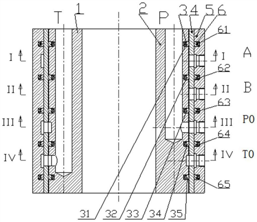
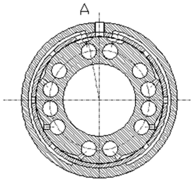
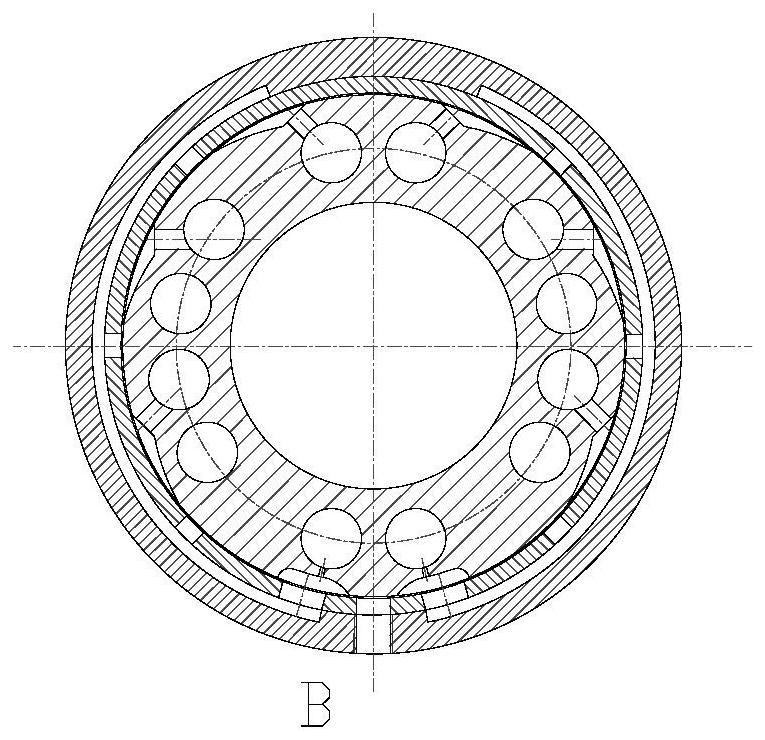
[0034] Such as Figure 1-5As shown, the present invention provides a large-flow axial distribution servo valve, including the internal axial distribution valve core rotor 2, the axial distribution valve sleeve 4, the external axial distribution valve body stator 5, and the corresponding rotor seal ring 3 and stator seal The ring 6, the shaft distribution valve sleeve 4 and the shaft distribution valve body stator 5 are cold assembled, and a through hole is opened at the center of the axis of the shaft distribution valve rotor 2 to reduce the mass of the shaft distribution valve rotor.

[0035] By adjusting the shaft distribution valve core rotor 2 to rotate to different angles, the continuous proportional communication between the working oil port, the oil supply port and the oil return port is realized, and the continuous different proportional speed control of the action of the actuator is realized within a specific rotation angle range. It can keep the state of the actuator...


PUM


Abstract

The invention relates to a large-flow axial flow distribution servo valve, comprising an axial flow distribution valve body stator, an axial flow distribution valve valve sleeve and an axial flow distribution valve core rotor. Four stator sealing areas, the shaft distribution valve core rotor is separated from top to bottom into four rotor sealing areas that are not connected to each other, and the shaft distribution valve body stator corresponds to the four sealing areas from top to bottom respectively. A working oil port A, a working oil port B, an oil supply port and an oil return port are opened, and the shaft distribution valve core rotor is provided with a plurality of oil supply channels, a plurality of oil return channels along the axial direction, and is used to reduce the mass and increase the torque. The through hole of the rotating shaft distribution valve core rotor realizes the continuous proportional communication control between the oil supply channel and the oil return channel and the working oil port A and the working oil port B respectively, and then realizes the continuous different proportional speed control of the external actuator. Compared with the prior art, the present invention has the advantages of large flow capacity, reduced rotational wear and the like.

Description

technical field [0001] The invention relates to the technical field of fluid control, in particular to a large flow shaft distribution servo valve. Background technique [0002] From the end of the 18th century to the beginning of the 19th century, Europeans invented the principle of single-stage jet pipe valve, single-stage single-nozzle baffle valve, and single-stage double-spray group baffle valve. During World War II, with the emergence of new materials, people Solenoid and torque motor were invented, and then two-stage electro-hydraulic servo valves and two-stage electro-hydraulic servo valves with feedback came out one after another. In the 1960s, most electro-hydraulic servo valves were two-stage servo valves with feedback and torque motors. , Aerospace and military fields have appeared highly reliable multi-redundant electro-hydraulic servo valves. [0003] There are many types of electro-hydraulic servo valves. At present, there are mainly double-nozzle baffle elec...

Claims


Application Information

Patent Timeline
Patent Type & Authority Patents(China)
IPC IPC(8): F15B13/02F16K11/085
CPCF15B13/022F16K11/085
Inventor 訚耀保张玄刘小雪
Owner TONGJI UNIV
Why Eureka
Try Eureka