Track geometrical morphology detection device

A technology of geometric shape and detection device, which is applied in the direction of measuring device, optical device, surveying and navigation, etc., can solve the problems of large investment of manpower, difficulty in equipment erection, inability to measure the height difference of double-track gauge and double-track at the same time, and smoothness of single track, etc.

Pending Publication Date: 2021-06-08
大连达发科技有限公司
View PDF0 Cites 0 Cited by
  • Summary
  • Abstract
  • Description
  • Claims
  • Application Information

AI Technical Summary

Problems solved by technology

The detection items are single, and it is impossible to measure the double-track gauge, the height difference of the double-track, and the smoothness of the single-track at the same time. There is no automatic measurement function of the spot position, which needs to be interpreted by the naked eye, and the error is relatively large; there is no automatic crawling function. When it is necessary to move the measurement point continuously, the risk factor of the operation is increased; the lack of automatic leveling function results in a large measurement error
Low efficiency, large investment of manpower, mostly high-altitude operations, difficult equipment erection, and certain potential safety hazards
[0003] It is imperative to carry out synchronous intelligent measurement of geometric forms such as track gauge, height difference, and smoothness. At present, there is no such instrument and equipment at home and abroad. Fill in the gaps at home and abroad

Method used


Image

  • Track geometrical morphology detection device
  • Track geometrical morphology detection device
  • Track geometrical morphology detection device

Examples


Embodiment Construction

[0033] The track geometry detection device of the present invention is as Figure 18 As shown, it includes two reference light sources, a gauge detection vehicle and an elevation detection vehicle. The two reference light sources are placed on the two measured rails. On the track to be tested, there is a wireless communication connection between the gauge detection vehicle and the elevation detection vehicle.

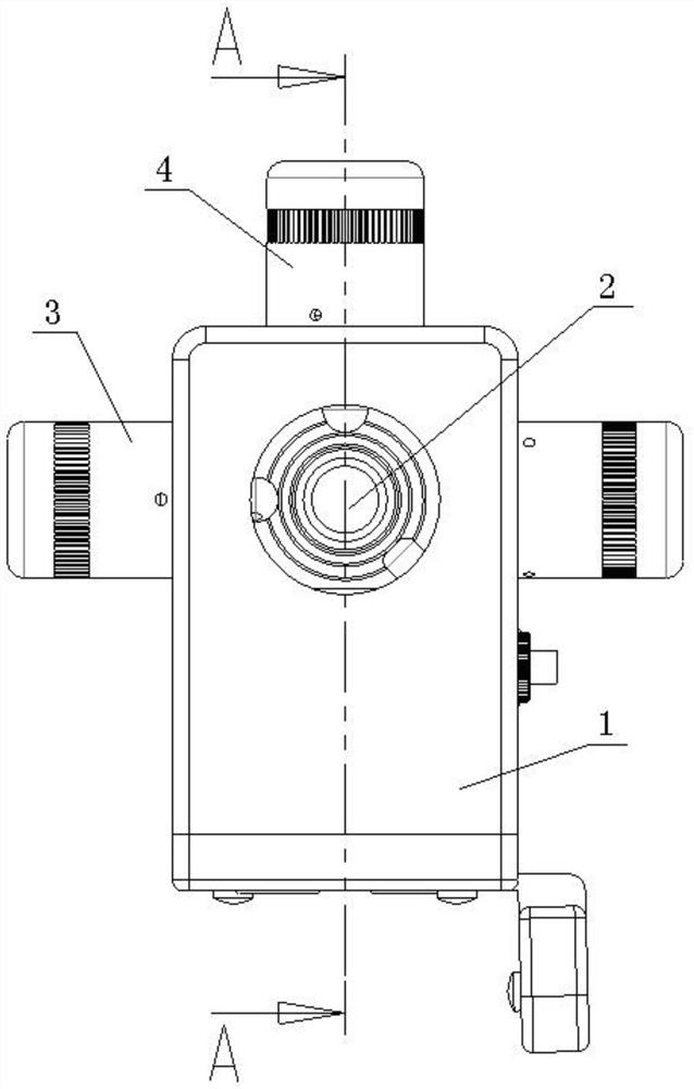
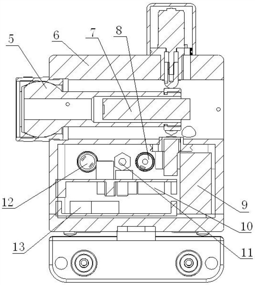
[0034] Such as Figure 1-4 As shown, a reference light source laser 7 is installed inside the front side of the reference light source casing 1 of the reference light source, and a reference light source laser emission port 2 is provided on the quasi-light source casing 1 corresponding to the reference light source laser 7, and a reference light source lithium is installed in the reference light source casing 1. Battery 9, reference light source driving board 10 and reference light source control main board 13, reference light source lithium battery 9 is connected to r...


PUM


Abstract

A track geometrical morphology detection device comprises two reference light sources, a track gauge detection vehicle and an elevation detection vehicle, the two reference light sources are placed on two detected tracks, the track gauge detection vehicle and the elevation detection vehicle are placed on the two detected tracks opposite to the two reference light sources respectively, and the track gauge detection vehicle and the elevation detection vehicle are in wireless communication connection. The reference light source is in wireless communication with the smoothness measuring target, the target center is automatically aligned, and the detection efficiency is improved; a light spot energy center detection technology is adopted, so that errors caused by manual reading are reduced, and the measurement precision of height difference and smoothness is improved; the gauge detection vehicle and the elevation detection vehicle are additionally provided with automatic leveling and dynamic adjusting functions, so that the measurement precision is effectively improved; the track gauge, elevation, smoothness and track inclination angle measurement are integrated, and the functions are rich; and the track gauge detection vehicle and the elevation detection vehicle can automatically crawl for measurement according to a set measurement interval and automatically return after measurement is completed, personnel following is not needed, and the safety coefficient of high-altitude operation is increased.

Description

technical field [0001] The invention relates to the technical field of track detection. Background technique [0002] At present, the geometric shape measurement of cranes or railway tracks uses instruments such as total stations, levels, and theodolites to measure each point on the track one by one to obtain the required track parameters. The detection items are single, and it is impossible to measure the double-track gauge, the height difference of the double-track, and the smoothness of the single-track at the same time. There is no automatic measurement function of the spot position, which needs to be interpreted by the naked eye, and the error is relatively large; there is no automatic crawling function. When it is necessary to move the measurement point continuously, the operation risk factor is increased; the lack of automatic leveling function results in large measurement errors. The efficiency is low, the investment of manpower is large, most of them are high-altit...

Claims


Application Information

Patent Timeline
IPC IPC(8): G01B11/14G01S17/08G01B11/02G01B11/30G01C9/00
CPCG01B11/14G01S17/08G01B11/02G01B11/30G01C9/00
Inventor 吴遵红倪涛孟庆海姚进刘伟
Owner 大连达发科技有限公司
Why Eureka
Try Eureka