Supporting seat

A technology of support base and support column, which is applied to optics, instruments, camera bodies, etc., can solve the problems of increasing the difficulty of adjusting the lens, loosening the bolts, and not easy to loosen, so as to avoid the loss of screws and nuts, reduce The use of parts and the effect of simple and convenient operation

Active Publication Date: 2021-06-08
PEGATRON
View PDF13 Cites 0 Cited by
  • Summary
  • Abstract
  • Description
  • Claims
  • Application Information

AI Technical Summary

Problems solved by technology

[0005] 2. After the user loosens the bolts, the lens is in a free state relative to the support frame. The user must hold the lens after adjusting the angle with one hand, and try to tighten the bolts with the other hand. Often after the bolts are tightened, the previously adjusted angle different
[00

Method used


Image

  • Supporting seat
  • Supporting seat
  • Supporting seat

Examples


Embodiment Construction

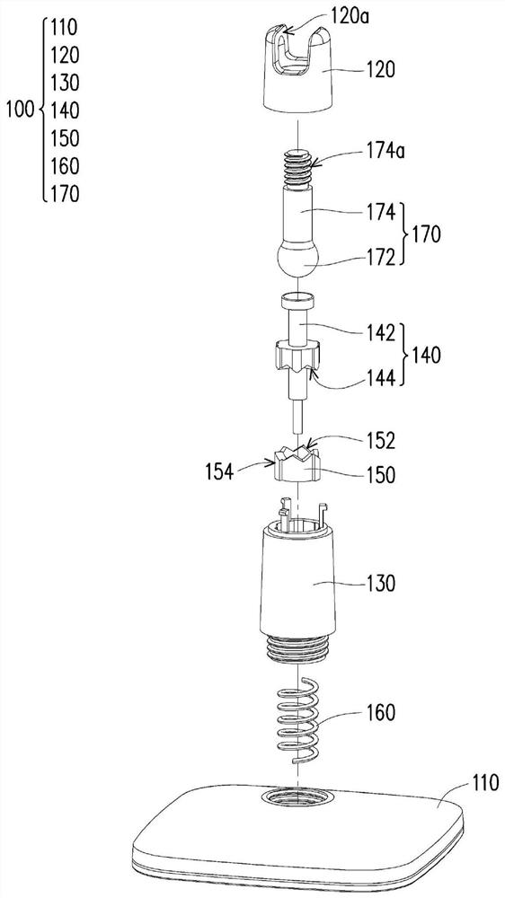
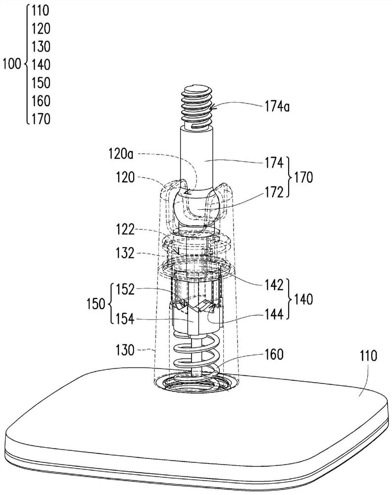
[0056] figure 1 It is an exploded schematic view of the support seat of the embodiment of the present invention, and figure 2 for figure 1 Schematic diagram of the assembly of the support base. Please also refer to figure 1 and figure 2 , the support base 100 of this embodiment is used to support an object, wherein the object may be a surveillance camera or a network camera, but is not limited thereto.

[0057] The supporting base 100 includes a base 110 , a limiting base 120 , a fixing base 130 , a supporting post 140 , a slide rail 150 , an elastic element 160 and a ball shaft 170 . The base 110 can be made of metal or plastic, wherein the base 110 is used to be fixed to a reference surface (not shown), and the reference surface can be a desktop or a wall, which is selected according to actual needs.

[0058] The material of the limiting seat 120 and the fixing seat 130 can be selected from plastic or metal according to requirements, wherein the fixing seat 130 connec...


PUM


Abstract

The invention provides a supporting seat. The supporting seat comprises a base, a limiting seat, a fixing seat, a supporting column, a sliding rail piece, an elastic element and a ball shaft. The fixing seat is connected with the base and the limiting seat and provided with an inner sliding rail. The supporting column is arranged between the base and the limiting seat and provided with a lower sliding rail part. The sliding rail part is arranged in the fixing seat, the sliding rail part is provided with an upper sliding rail part which is in contact with or separated from the lower sliding rail part, and the upper sliding rail part can move, rotate or stop relative to the fixing seat through structural matching with the inner sliding rail; the elastic element abuts against the base and the sliding rail part. The ball shaft is provided with a ball part and a shaft part, the ball part is limited in the limiting seat, the shaft part protrudes out of the limiting seat, and the upper sliding rail part, the lower sliding rail part and the inner sliding rail are matched to drive the supporting column to abut against or move away from the ball part so as to fix or release the ball shaft.

Description

technical field [0001] The invention relates to a support base, in particular to a support base for supporting an object. Background technique [0002] In daily life, photographic lenses are often used for long-term photography, such as surveillance lenses or webcams. Because this type of monitor must maintain a fixed shooting angle for a long time, it usually uses a support frame to support and fix the shooting angle of the lens. Existing lens support frames usually have long slots or arc-shaped slots on the frame body, and use screw locks to fix the position of the lens relative to the frame body. Usually, when changing the shooting angle of the lens, it is necessary to remove the screw first, adjust the position of the lens on the frame body, and then use the bolt to fasten the lens and position it. [0003] However, this architecture has the following problems: [0004] 1. The user needs to use a hand tool, such as a screwdriver, to loosen and tighten the bolts to adj...

Claims


Application Information

Patent Timeline
IPC IPC(8): G03B17/12
CPCG03B17/12
Inventor 游佳颖
Owner PEGATRON
Why Eureka
Try Eureka