Opening electromagnet of spring operating mechanism
An operating mechanism and electromagnet technology, applied in circuits, electric switches, electrical components, etc., can solve the problems of unstable low-voltage tripping and difficult design, and achieve easy control, avoiding insufficient space, and convenient disassembly and assembly Effect
- Summary
- Abstract
- Description
- Claims
- Application Information
AI Technical Summary
Problems solved by technology
Method used
Image
Examples
Embodiment 1
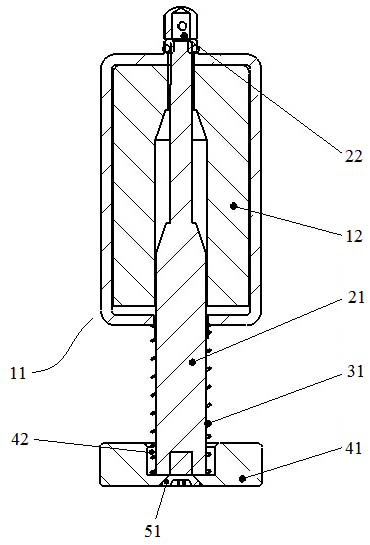
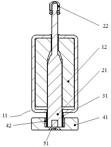
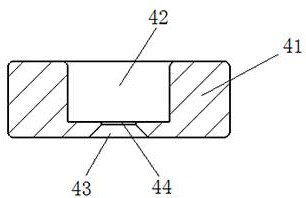
[0036] Such as figure 1 with figure 2 As shown, the opening electromagnet of the spring operating mechanism is the opening electromagnet used by the spring operating mechanism in the vacuum circuit breaker, including the electromagnet main body 11, the moving iron core 21, the return spring 31 and the delay counterweight 41, It is transformed on the basis of the existing opening electromagnet. The specific transformation content is to remove the spring seat at the rear end of the original moving iron core 21 and replace the delay counterweight 41.
[0037] The structure of the electromagnet main body 11 can adopt the structure in the prior art, and a coil 12 is arranged inside, and a moving iron core 21 is pierced in the coil 12 . The front end of the moving iron core 21 passes through the electromagnet main body 11, and a collision block 22 is fixed on the passing part, which is used to extend forward under the drive of the coil 12 to hit the opening pinch of the operating ...
Embodiment 2
[0041]The difference between this embodiment and Embodiment 1 is that in Embodiment 1, the delay counterweight 41 is fixed on the rear end surface of the moving iron core 21 by screws 51, while in this embodiment, the delay counterweight 41 is fixed by riveting On the rear end face of the moving iron core 21. In other embodiments, after the weight of the delay counterweight 41 is determined, it can also be welded to the rear end surface of the moving iron core 21 .
Embodiment 3
[0043] The difference between this embodiment and Embodiment 1 is that in Embodiment 1, the delay counterweight 41 is a disc structure, while in this embodiment, the delay counterweight includes a base plate, and the front side of the base plate forms a spring stop surface , there are protrusions uniformly distributed along the circumferential direction on the front side of the substrate. Certainly, in other embodiments, the delay counterweight 41 may also be a plate-shaped structure, and in order to ensure that the delay counterweight 41 has a set weight, the radial dimension of the delay counterweight can be increased.
PUM
 Abstract
Description
Claims
Application Information
 - R&D
- Intellectual Property
- Life Sciences
- Materials
- Tech Scout
- Unparalleled Data Quality
- Higher Quality Content
- 60% Fewer Hallucinations
Browse by: Latest US Patents, China's latest patents, Technical Efficacy Thesaurus, Application Domain, Technology Topic, Popular Technical Reports.
© 2025 PatSnap. All rights reserved.Legal|Privacy policy|Modern Slavery Act Transparency Statement|Sitemap|About US| Contact US: help@patsnap.com


