Critically ill patient postoperative combined monitoring nursing device

A technology for critically ill patients and equipment, applied in the direction of flow monitors, flow control, control/regulation systems, etc., can solve the problems of patient safety hazards, reduce the use of space, and automatically replace patients' infusion tubes, so as to ensure safety and reduce Effects of Work Stress

Pending Publication Date: 2021-06-11
WUHAN UNIV
View PDF5 Cites 2 Cited by
  • Summary
  • Abstract
  • Description
  • Claims
  • Application Information

AI Technical Summary

Problems solved by technology

[0003] The existing postoperative monitoring and nursing equipment for critically ill patients is not perfect. Most of the patients are in a coma state after the operation. When the infusion device of the equipment performs infusion, the staff cannot guard the patient all the time, and the equipment cannot automatically infuse the patient. The tube can be replaced automatically in time, and the infusion tank cannot be automatically judged to be suitable for the replacement of the infusion tank, which wastes the labor of the medical staff, and at the same time poses a great hidden danger to the patient's postoperative safety. Adjust the speed of the infusion. If the infusion speed of the patient is too fast after the operation, if the infusion speed is not adjusted in time, it will easily lead to the safety of the patient. At the same time, the equipment needs to arrange multiple testing equipment and infusion equipment irregularly, and the space is messy, which increases the equipment. The use area is too large, the detection equipment and the infusion device cannot be combined, and the use space is reduced

Method used


Image

  • Critically ill patient postoperative combined monitoring nursing device
  • Critically ill patient postoperative combined monitoring nursing device
  • Critically ill patient postoperative combined monitoring nursing device

Examples


Embodiment 1

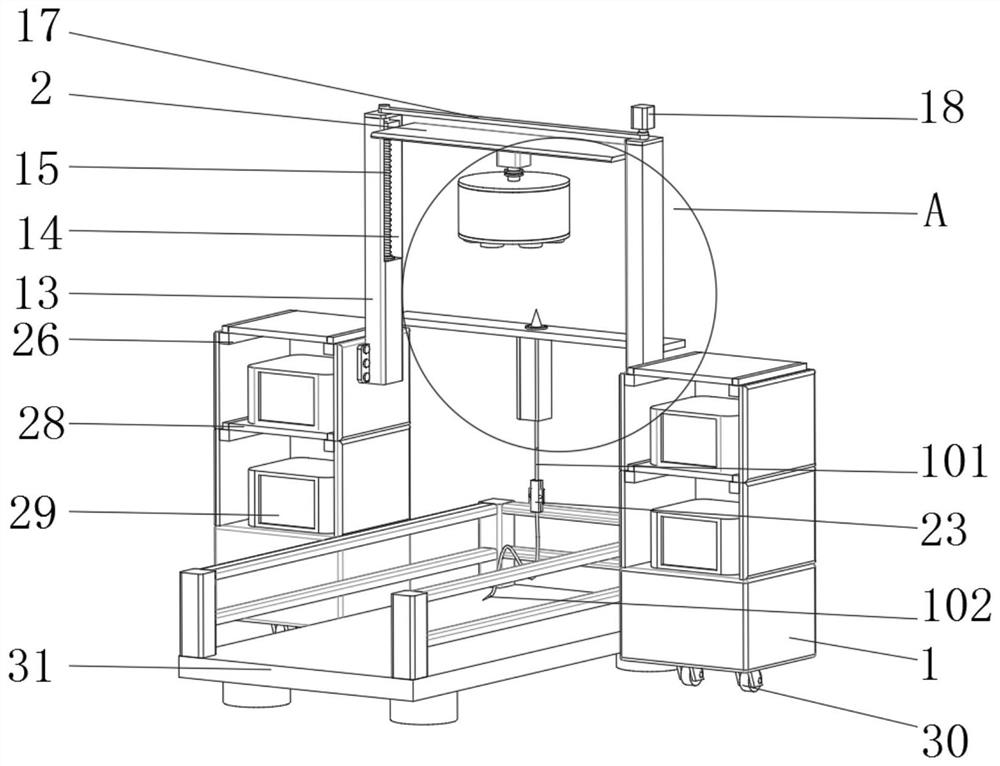
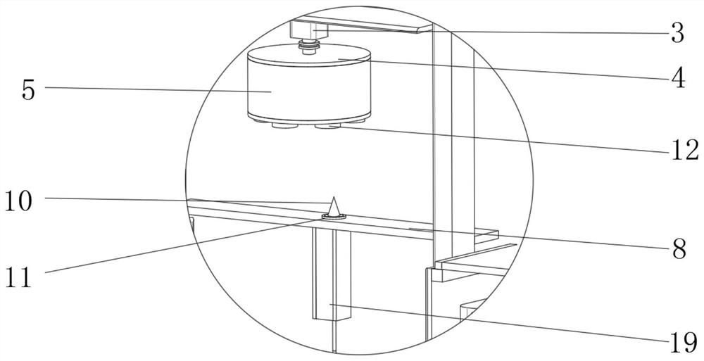
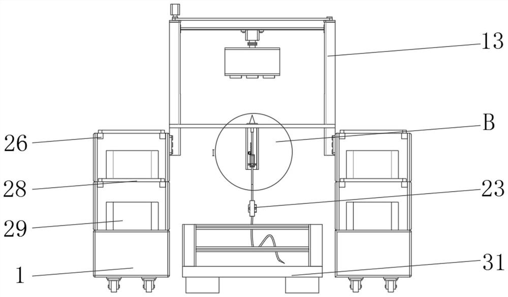
[0031] Such as figure 1 , 2 As shown in . The middle part of the bottom surface of the plate 2 is connected by bolts. The working end of the rotating motor 3 is provided with a rotating disc 4. The disk 5 is threadedly connected with the rotating disk 4, and the installation disk 5 is equipped with a liquid storage tank 7 in an array, the liquid storage tank 7 is fixed to the inner bottom of the installation disk 5, and the top of the liquid storage tank 7 is offset against the bottom of the rotating disk 4, The bottom of the installation disc 5 is provided with connecting holes 6 in an array, and the connecting holes 6 run through the bottom of the installation disc 5 and the liquid storage tank 7 at the same time, and a limit plate 8 is provided under the reinforcement plate 2, and a mounting hole 9 is provided on the top surface of the limit plate 8 , the mounting hole 9 runs through the top surface of the limiting plate 8, the mounting hole 9 is provided with an infusion...

Embodiment 2

[0033] Such as figure 1 , 2 , 4, postoperative combined monitoring and nursing equipment for critically ill patients, the bottom of the limiting plate 8 is provided with a fixed frame 19, the fixed frame 19 is welded to the bottom of the limiting plate 8, and one side of the fixed frame 19 is provided with a stepping motor 20, The stepper motor 20 is connected with one side of the fixed frame 19 by bolts, the working end of the stepper motor 20 is fixed with a gear 21, the fixed frame 19 is provided with an infusion controller 22, and the infusion controller 22 is fitted with a concave top surface on the surface of the infusion pipeline 101. U-shaped grooves 221 are provided on both sides of the infusion controller 22, and the U-shaped grooves 221 run through both sides of the infusion controller 22. The infusion controller 22 is provided with a roller 222, and the two ends of the roller 222 are fitted in the U-shaped In the groove 221, the two ends of the roller 222 are fixe...

Embodiment 3

[0035] Such as figure 1 , 3 As shown in , 6, combined monitoring and nursing equipment for critically ill patients after surgery, a heater 23 is provided on the surface of the infusion pipeline 101, and the infusion pipeline 101 is fitted in the groove on the top surface of the heater 23, and the infusion pipeline 101 and the top surface of the heater 23 are concave. The grooves offset each other, and the heater 23 is provided with a storage groove 24. The storage groove 24 is a blind groove, and the heating sheet 25 is embedded in the storage groove 24. The heater 23 is used in the present invention, and the infusion pipeline 101 is embedded in the heater 23 In the groove on the top surface, the two ends of the heater 23 are fixed by bolts, and the infusion pipeline 101 is fixed against the groove on the top surface of the heater 23. When it is cold, the heating plate 25 in the storage tank 24 of the heater 23 is activated. The surface of the infusion pipeline 101 is heated ...


PUM


Abstract

The invention discloses a critically ill patient postoperative combined monitoring nursing device, and relates to the technical field of medical equipment, the critically ill patient postoperative combined monitoring nursing device comprises a supporting base, a reinforcing plate is arranged above the supporting base, a rotating motor is in threaded connection with the middle of the bottom surface of the reinforcing plate, a rotating disc is in key connection with the working end of the rotating motor, and a disc is installed at the bottom of the rotating disc through threads; liquid storage tanks are fixed in the mounting discs in an array mode, the tops of the liquid storage tanks abut against the bottom of the rotating disc, connecting holes penetrate through the bottoms of the mounting discs in an array mode, a limiting plate is arranged below the reinforcing plate, mounting holes penetrate through the top face of the limiting plate, infusion needles are arranged in the mounting holes and embedded in the mounting holes, and electromagnets are in threaded connection with the bottoms of the infusion needles. By adopting the rotating disc, the liquid storage tank, the electromagnet and the infrared liquid measuring device, a patient can automatically replace an infusion medicine bottle without being cared by medical staff after an operation, the time for replacement is automatically judged, the working pressure of the medical staff is reduced, and the safety of the patient after the operation is effectively guaranteed.

Description

technical field [0001] The invention relates to the technical field of medical equipment, in particular to postoperative combined monitoring and nursing equipment for critically ill patients. Background technique [0002] Medical equipment refers to instruments, equipment, utensils, materials or other items used alone or in combination for the human body, including the required software. Medical equipment is the most basic element of medical treatment, scientific research, teaching, institutions, and clinical disciplines, including professional medical equipment and household medical equipment. Medical equipment is the basic condition for continuously improving the level of medical science and technology, and it is also an important symbol of modernization. Devices have become an important area of ​​modern medicine. The development of medical care depends to a large extent on the development of instruments. Even in the development of the medical industry, its breakthrough i...

Claims


Application Information

Patent Timeline
Patent Type & Authority Applications(China)
IPC IPC(8): A61M5/14A61M5/162A61M5/168A61M5/44
CPCA61M5/1415A61M5/1408A61M5/1413A61M5/162A61M5/16813A61M5/1684A61M5/16877A61M5/445
Inventor 罗力王庆兰
Owner WUHAN UNIV
Why Eureka
Try Eureka