Multifunctional medical care lamp
A multi-functional, irradiating lamp technology, applied in phototherapy and other directions, can solve the problems of inaccurate adjustment of irradiation distance and reduced treatment effect
- Summary
- Abstract
- Description
- Claims
- Application Information
AI Technical Summary
Problems solved by technology
Method used
Image

Examples
Embodiment Construction
[0021] Further detailed explanation through specific implementation mode below:
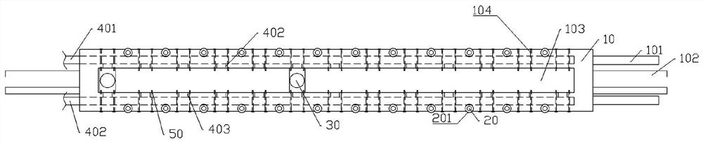
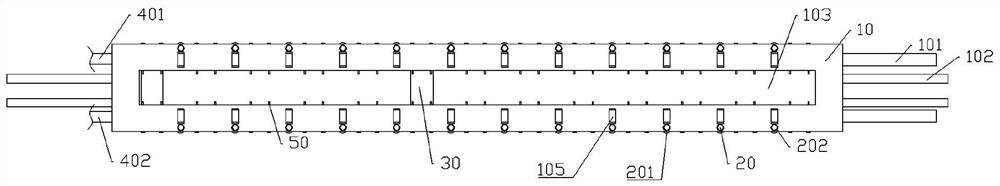
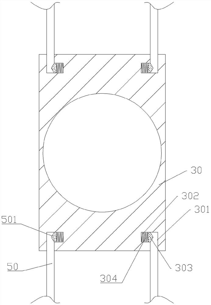
[0022] The reference signs in the accompanying drawings of the description include: installation strip 10, binding strap 101, binding strip 102, through slot 103, first socket 104, fixing ring 105, support rod 20, suction cup 201, installation ring 202, illumination lamp 30 , the second socket 301 , the insertion hole 302 , the wedge 303 , the spring 304 , the first electric wire 401 , the first terminal 402 , the second electric wire 403 , the second terminal 404 , the insertion rod 50 , and the notch 501 .
[0023] The embodiment is basically as attached figure 1 , attached figure 2 And attached image 3 Shown: a multifunctional medical care lamp, including a flexible installation strip 10, a number of lamps 30, a power supply unit, a number of insertion rods 50 and a number of support units, the installation strip 10 is strip-shaped, and the installation strip 10 is made of high-strength re...
PUM
 Abstract
Description
Claims
Application Information